This thread has been locked.

If you have a related question, please click the "Ask a related question" button in the top right corner. The newly created question will be automatically linked to this question.

LM25011AMYE

Other Parts Discussed in Thread: LM25011

Hello.

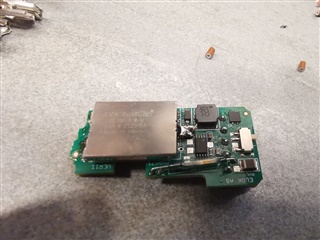
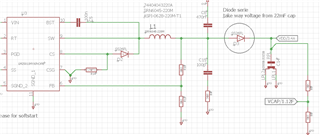
I have made a design with LM25011MY/NOPB. project is charging a capacitor 22mF ( 0,022 F) to power a coil.

The board working properly.

order LM25011AMYE because it was not too long delivery time for the component. 

produce but board not work.

first power-up, it is normal , V out is 8V and drive the coil properly. 

when if I turn off power and turn off , the output voltage decrease to less 2V and than restart the LM25011AMYE and give 8V again!!!

Because the 22mF capacitor it takes 1 minute to restart!!!! 

Can propose some fix.

  • Hello, Can you provide the schematic you utilized for your evaluation of the product?

    In addition, do you have any waveforms to provide? I would like to see Vin voltage, SW voltage, and Vout voltage.

  • 483_2021_V11_COMUS.pdf

    this the schema for the power parts.

    for signal it is not easy.

    all parts are under the capacitor for 22mF .

  • Thanks, I hope to follow up with you on the review, Monday.

  • Hello,

    I re-read your post a bit more carefully. To me it sounds like you say the the input voltage is turned off but the device restarts even without input voltage?

    If that is the case, it sounds as if the output is feeding back to the input through the high side body diode. 

    Unfortunately, without this device having external UVLO, there is nothing to prevent that from happening, unless you can establish a bleeder on the output to ensure that the output voltage is below the VIN ulvo -minus a diode drop.

    Hopefully I understood your question.

    If you have any illustrations to provide of the phenomena I can review that.

  • not quite like this.

    when the output capacitor is discharged , the regulator works properly. Charge the capacitor to 8V, drive the coil all perfect.

    I turn off power, no input voltage 0V , but the output capacitor has some voltage. if I turn on power input, if the output voltage is over 2V the IC do not restart.

    the capacitor is 22000uF 0,022F 

    it is more clear? this problem is only for LM25011AMYE , it works properly with  LM25011MY/NOPB

    order the "A" version because waiting a lot of months and not get the normal parts.

    Thank you for your help.

  • Oh, I see.

    It seems like you are suggesting that the device does not start with pre-biased output.

    I will see if we have encountered issues with pre-biased output on this architecture. From the datasheet alone and my understanding of the device, I do not see what would cause pre-biased output startup issues.

    Allow me to get back to you.

  • Hello,

    Can you please provide waveforms of Vin, Vout, and inductor current during the failure?

    I will need to take a look if my understanding is correct to diagnosis the issue.

  • Vin and Vout no problem but how do you measure the inductor coil???? it is SMD and I do not have a device to read this. 

    in the datasheet for the version "A" 

    1) The LM25011A has a shorter minimum off-time than the LM25011

    I do not think it is a problem

    2) "Ripple voltage, which is required at the input of the regulation comparator for proper output regulation, is generated internally in the LM25011, and externally when the LM25011A is used." 

    Not sure what it means but if must be externally , I do not have done?

    3) "When the LM25011 operates in current limit, the on-time is reduced by approximately 40% (this feature is not present in LM25011A)."

    What does this feature?

  • Hello, you could consider adding a series resistance and measure the voltage across it differentially to examine inductor current. It maybe a bit difficult without a clip-on current probe.

    You can then measure Vin, Vsw, Vout, iL.

    Maybe you can connect some leads to the capacitor to allow for easier measurement, as I understand the issue with board assembly.

    2. The device requires ripple injection for stability. From your description, it does not seem to be the problem, but I can address the concern as well. The non-A version has the ripple injection needed for the COT architecture stability, emulated, internally, thus no need for additional circuitry.

    See section 8.2.2 Output Ripple Control

    3. The device has current limit, though, the on-time is not reduced. It will continue to operate at constant on time with peak current limit engaged.

  • ok thank you. 

    1) measure current I will see but resistor is not one option  in serie with the coil, will try to see current on the power line because it is only the LM25011A to use current in the start up. 

    2) ripple injection.

    well, it is easy to solder these 2 cap and resistor for testing but if the output is not active the ripple circuit will have not to effect?! 

    3) I will use a diode series with the capacitor of 22mF to see if it is my problem perhaps I can get the same problem with LM25011 for special situations.

    we have not produced a lot of board it was a long design. først we try with a 5V capacitor with 33mF but the coil need 6V and the power on it was too low.

    We have made 200 pieces with LM25011 and now only 12 of 100 with LM25011A ( stop production after testing the first panel). 


  • 1) I think you will run into issues measuring the AC input current. It is supported by the caps. You maybe able to squeeze in power sense resistor in series with the output inductor, with positioning them at an angle.

    2) the ripple injection ensures stability across Vin range, as well output loading. 

    3). I am unsure that I am following your suggested debugging step. Maybe you can provide an illustration?

  • i hope you can see the new diode. I will try this week end. 

  • Hello Thierry, 

    Let us know when you try restarting the circuit with the diode. 

    Regards, 

    Denislav

  • YOU WILL GET SOME INFO MONDAY. 

  • Test with a serie diode like the picture you get.

    it is working, well I must see more because I feeling it is slow. But I do not believe i feeling in electronics I will make some measure to see. 

    but the problem was the voltage on the out capacitor with the LM25011A 

  • Hello Thierry Pottier,

    Given your high output voltage, the device precharge FET may have some issues with discharge pre charge on the output to enable to the BOOT cap to charge up.

    The series diode you utilized is preventing SW from seeing the pre bias.

    You could consider some minimal load on the output to discharge the output cap to enable quicker restart, or, alternatively, have diode from Vin to CBOOT thru current limiting resistor. Voltage protection on CBOOT would be needed in that case to ensure you dont charge CBOOT over its absmax.

  • Yes I agree with your analysis but I can not discharge the capacitor because I use this energy to drive a coil of 2 ohms but when the voltage on the CPU is lower than reset then it is about  2V left and block the driver. 

    But because it is not possible to order the LM25011MY/NOPB and this capacitor, will set the project on standby. 

    Thank you for your support and nice to find the problem. it can be possible to redesign the board with a diode serie. 


  • Good to hear. Let me know if additional support is needed.