This thread has been locked.

If you have a related question, please click the "Ask a related question" button in the top right corner. The newly created question will be automatically linked to this question.

TPS61023: duty runaway query

Part Number: TPS61023
Other Parts Discussed in Thread: TPS61022

Hi,

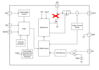
This question could pertain to any boost although I'm using TPS61022 and TPS61023 in two designs so might as well focus on them.

For a boost, in the situation where the input voltage is too low to create the requested output voltage (at a given current) the low FET's go to a duty % which actually causes the output to drop. The duty then continues to increase and the situation becomes worse shorting much of the current through the FET and yielding heat which usually destroys the IC. What measures do the 61022 and 61023 employ to stop this situation occurring? I use these chips specifically because they're both suited for super-capacitor use where the input voltage is low but current potentially extremely high. 

Cheers, Andrew


  • Just for confirmation, I'm asking what happens when the output voltage can't meet regulation and the lower FET duty increases as runaway condition. I expect that in position marked X there would need to be voltage monitoring. While the inductor charges there is zero volts but once it saturates a voltage would present across the FET. The diagram from 61022/3 does not show anything here.

  • Hi Andrew,

    Thanks for questions. Your case exists when minimum toff time has been triggered so that the energy delivered to output side does not meet load requirement, so Vout drops. However, the issue which may exist in fixed frequency control does not exist in TPS61022/023. The reason is TPS61022 and TPS61023 has ability to adaptively decrease switching frequency when Vin goes very low. This helps converter to deliver enough energy to hold Vout.

    TPS61022/TPS61023 switching frequency:

    For any boost converter, we have toff=Vin*efficiency/Vout/Fsw. When Vin goes low, Fsw also decreases and toff is extended, so that minimum toff is not triggered.

    -Wenhao

  • Yes but what about when the voltage isn't very low?

    Consider a situation where input = 1.8v, output = 5.5v (requested) and output current is as such that the output drops to 4v. In this case the IC will increase the duty to try and boost the voltage. It might manage to do so, but assume it doesn't and the inductor saturates causing a huge loss in efficiency, how does the IC know to back off the duty at that point if it's not measuring the voltage across the lower FET?

  • Actually I think I understand now. The max current detect needs to trigger before inductor saturation, so it's just a case of ensuring this. Using an inductor which can potentially saturate before the max current limit runs the risk of the behaviour I described.

  • Hi Andrew,

    We do not recommend use inductor which has saturation current lower than 10A+maximum inductor ripple+some margin. For example, if calculated inductor current ripple is 2A, then I would recommend practically 12*120%=14.4A minimum saturation current. 

    If inductor is chosen lower than that, LSFET would be the most risk one as the peak current can go unpredictably high and when LSFET is OFF, high SW-GND voltage stress may break the FET.

    -Wenhao

  • Thanks, that's a very large margin (and size of inductor!) for 2A+peak.

  • Hi Andrew,

    For TPS61022, it is needed. For TPS61023, which has smaller valley current limit, you could use smaller inductor with smaller saturation current. Above is just an example how we usually choose inductor saturation current rating, as your reference.

    -Wenhao