This thread has been locked.

If you have a related question, please click the "Ask a related question" button in the top right corner. The newly created question will be automatically linked to this question.

LM34936: CBulk Selection & M1 Issues

Part Number: LM34936

Hi,

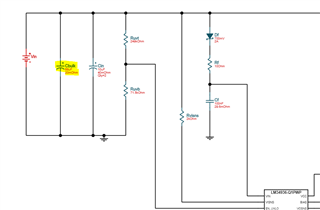
I am using the LM34936 Buck-Boost controller in my circuit based on the WEBench reference design. I have a question in relation to the selection of CBulk. Do you see there being an issue when selecting the CBulk as 39 uF versus the recommended 68 uF in the WEBench reference design? The typical output current is approximately 2 A during normal operation.

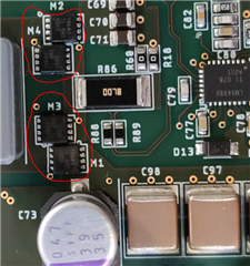
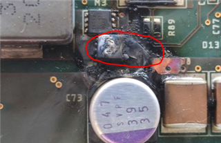
The following issue occurred in relation to the MOSFET M1 (see image below). Would you have any thoughts on what could cause this damage? For example would a short between the gate & source cause this as, based on the MOSFET datasheet, the absolute maximum voltage is +/- 20 V while the input voltage in my system is 24 V. 

Any help with these points would be greatly appreciated. 

All the best, 

Dave.

  • Hello Dave,

    In general the bulk capacitor is just making sure that the input voltage rail is stable, so the exact value only defines how much ripple you will have on the input voltage.

    This damage looks like a high current or power damage. But it is almost impossible to guess what happened.

    Please check how much current you allow in your design (the sense resistor is defining this) and if the power you want to dissipate on this transistor is using the transistor in the save operating area.

    BTW, in general you should have the ceramic caps closer to the transistor than the bulk cap as the ceramics react faster on current changes.

    I would recommend to check on good boards how such a damage could happen, e.g. by connecting adjacent pins.

    Best regards,
    Brigitte

  • Hi Brigitte,

    Thanks very much for your reply, it is greatly appreciated. I am trouble shooting the problem (including shorting neighbouring pins). Thanks for the feedback on the capacitors, I will make this change going forward. I have another question in relation to the MOSFETs, see image below of the MOSFETs located on the PCB 

    Do you see there being an issue with the proximity of the MOSFETs to each other? This does deviate from the recommended WEBench design so just want to confirm. Thanks again for your help and I look forward to hearing from you. 

    Kind regards,

    Dave.  

  • Hello Dave,

    The layout around the MOSFETs is more important than the placement, but the layout is normally somehow defined by the placement. Please review the EVM for the right placement and layout.

    Best regards,
    Brigitte