This thread has been locked.

If you have a related question, please click the "Ask a related question" button in the top right corner. The newly created question will be automatically linked to this question.

CSD17313Q2: CSD173113Q2 turn on vs PSpice

Part Number: CSD17313Q2

Hi Team,

Please see my test and simulation data below.  My questions are:

1. Will the CSD17313Q2 simulation model accurately predict Crss in the datasheet?

2. Is there a method to accurately predict the miller plateau voltage with different Vds values?  My test results match the PSpice simulation, however figure 4 in the datasheet is higher.

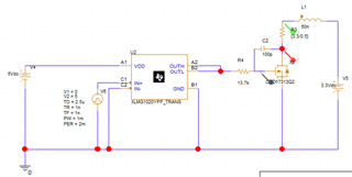
I am using the CSD17313Q2 in a resistive load application. I am using the LMG1020YFFR as the gate driver.  In this test data my series gate resistor is 13.7k ohms, although I have test data for smaller and larger values if we need it.  The PSpice simulation snapshot is shown below, however I need to add 100 pF miller capacitance to get the simulation to line up with the measurement.  I have purposely eliminated the PCB parasitics where I could, however did not notch out the internal layers underneath the MOSFET as I anticipated just 5-10pF of interplane capacitance.  I am surprised that I need 100pF additional Crss in the PSpice simulation to match my test data.

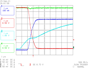
Channel 1 = Blue = Ids
Channel 2 = Red = Vds
Channel 3 = Light Blue = Vgs = 0V to 10V
Channel 4 = Green = 3.3V

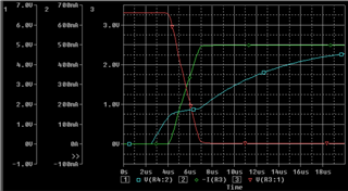
The simulation below shows the results with 100pF added as shown in the schematic.

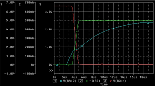
The simulation below shows the results without any additional capacitance added.

Thanks,

Stephen

  • Stephen,

    Thanks for the interest in our FETs. John is back in the office tomorrow and will answer this post then, he is our FET modeling expert.

    Best Regards'

    Chris

  • Thanks Chris.  I'm looking forward to John's feedback.

    Thanks,

    Stephen

  • Hi Chris,

    I just reviewed the data in this forum post, and actually the test data is much closer to the simulation (without extra capacitance) than I thought.  I was reading the timebases incorrectly (1us vs 2us / div). I must have been reviewing the test data with 27.4k series gate resistance instead of 13.7k series gate resistance.  I verified that the model and test data are off only by 5-10pF.  That takes care of the question on the model and Crss.

    I still need a response on question #2 and predicting the plateau voltage.

    Thanks,

    Stephen

  • Hi Stephen,

    I am not aware of a method to predict the Miller plateau voltage at different values of VDS. I'll need to research this. We do compare model results for capacitance to the characterization data collected during product development. I'd like to move this discussion to regular email. I will send you an email.

    Thanks,

    John Wallace

    TI FET Applications