This thread has been locked.

If you have a related question, please click the "Ask a related question" button in the top right corner. The newly created question will be automatically linked to this question.

LM62440-Q1: EMC improvement

Part Number: LM62440-Q1

Hi Sir,

To improve EMC products,

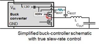
They connected a 10 ohm resistor between R boot and SW of lm62440-q1 chip,

And the SW pin is directly connected to the ground and has a 10pF capacitor,

In addition, a 4.7 ohm resistor is connected in series between C boot and R boot.

Does the above affect the circuit function?

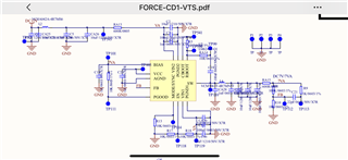
R5 = 4.7 Ω, ra14 = 10 Ω, ca28 has been changed from 1NF to 10PF.

The problem now is that when the customer's products fluctuate at low pressure (3V − 9V),

The chip temperature is very high, and there is a chance of short circuit. After changing R5 to 0 Ω, the temperature is normal,

However, we are not sure about the impact of ra14 and ca28 on the design, so we would like to hear your suggestions.

Thanks.

  • Hi,

    The RBOOT pin should have a resistor connected to CBOOT to adjust the internal high-side MOSFET's slew rate. Increasing the resistor will slow down the slew rate and help reduce EMI. First off I would start with having a capacitor between CBOOT and SW. Then I will have a resistor connecting RBOOT directly to CBOOT pin for "true slew rate control". The device has a RBOOT for a dedicated resistor. This removes the boot UVLO concern and reduces the noisy surface area formed by the conventional CBOOT and RBOOT between SW and HDRV gate. 

    I'm not sure what the C18 and RA14 will create but if customer wants to have a snubber circuit then the RA14 resistor should be terminated to GND. A snubber circuit can be made from a series capacitor and resistor between SW and GND. Also suggest moving the CA28 after the inductor to act as a high frequency bypass capacitor.

    Regards,

    Jimmy