Because of the holidays, TI E2E™ design support forum responses will be delayed from Dec. 25 through Jan. 2. Thank you for your patience.

This thread has been locked.

If you have a related question, please click the "Ask a related question" button in the top right corner. The newly created question will be automatically linked to this question.

TPS65218D0: DCDC4 startup issue with temperature

Part Number: TPS65218D0
Other Parts Discussed in Thread: TPS51200, TPS65218

We're having an issue in our board after we've replaced the TPS65218B with the TPS65218D0. The design was based on the evaluation board:

www.ti.com/.../TMDXSK437X

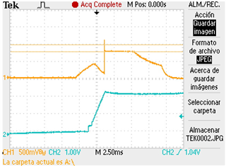
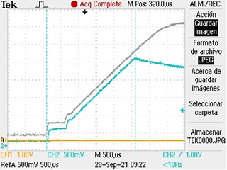
After having replaced the old PMIC with the new TPS65218D0, if we try to turn on the board above 50ºC, the DCDC4 doesn't complete the startup sequence.

After 2.5ms, this output stops regulating and turns off.

Until that moment, the other outputs are switched on correctly. Those that should be turned on next steps, remain off.

The following image shows a waveform of a normal start (gray color) together with the waveform of a failed start (blue):
Best regards.

  • Hi,

    I add some more information about the detected issue.
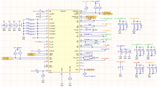
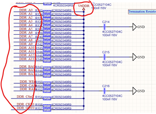
    The following image shows the PMIC schematic:

    The inductances on the DCDC[1: 3] are VLCF5020T-2R2N (TDK). The inductance used on DCDC4 regulator is SRN5040-4R7M (BOURNS). I've tried to change the inductance for DCDC4 (4.7uH) and I used also the VLCF5020T-2R2N (2.2uH), but the result is the same. I've also tried with different output capacitance values (increasing the number of capacitors) from 22uF to 200uF: the issue appears at different temperatures, but it keeps appearing.

    Regards.

  • Hi Amilcar,

    Thanks for reaching out! I'm looking into this issue and will provide an update by Thursday. 

    Thanks,

    Brenda

  • I think we've found the cause of the issue. The DCDC3 output goes to the TPS51200 (DDR rermination regulator for DDR3 memories).

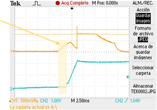
    When the voltage of the DCDC4 (+ 3.3V) reaches + 2.3V, that regulator turns on (blue DCDC4 output, and orange VttDDR output).

    The voltage at the output of the TPS51200 regulator rises before switching on because the supply voltage of the DDR3 (+ 1.5V) (DCDC3) is already there (but it is not relevant). An overvoltage is seen on the VO pin (output).

    This voltage spike also appears on the input pin of the LDO (+ 1.5V ... DCDC3 output...) (blue DCDC4 output, and orange DCDC3 output).

    So, we can see an overvoltage of about 80mV and 100us at the DCDC3 output. There is a VOV fault and and the PMIC stops the power-up sequence and shutdown.

    On TPS65218B1, the STRICT bit at reset is '0'. Then the PMIC starts normally.

    On TPS65218D0, the STRICT bit at reset is '1'. Then we're are having these issues at start up.

    I think  this bit should still be at '0' by default. Once the processor is turned on, it could reprogram this bit to '1'. But  the DCDC3 VOV is too sensitive on the startup sequence.

    Regards.

  • Hi Amilcar,

    Thanks for posting this question on E2E. Does everything work as expected if you change the STRICT bit to 0b? 

    Also, I don't understand why the TPS51200 gets enable before before the DCDC4 is high. My understanding is that DCDC3 is connected to the supply input voltage and DCDC4 provides the enable so even if DCDC3 is high, TPS51200 should stay disable until DCDC4 is turned on. Are the connections to on the TPS51200 correct? Here is what its datasheet says:


    Thanks,

    Brenda

  • Hi Brenda,

    the problem appears when voltage on DCDC4 goes above 2.3V. Then EN (pin 7) goes high (there's a pullup to VIN +3.3V) and TPS51200 gets enable. A + 300mV overvoltage appears on pin 3 which shouldn't be there if the regulator were stable. This overvoltage is transferred to the input of the regulator (DCDC3) and causes a VOV alarm at that output of the PMIC. With partnumber TPS65218B1, the VOV alarm was disabled in the PMIC power-up sequence. With part number TPS65218D0, the VOV alarm is active by default. The processor cannot modify any bit until the boot sequence is complete. But the boot process fails because of that surge problem on the TPS51200 output....

  • Hi Amilcar,

    Thanks for your message. I definitely see the overshoot on the VO pin of the TPS51200 when DCDC4 reaches ~2.4V. However, I have contacted the team who owns TPS51200 and they agree that VO should not start ramping up before EN (I'm referring to the highlighted area in the capture below). Here is some additional comments and questions:

    • Do you have a booster pack (BOOSTXL-TPS65218) or EVM that you could use to re-program the STRICT bit on the CONFIG1 register to see if this allows the system to power up? Please note that changing the STRICT bit to 0b will make the overvoltage not monitored. 
    • [Question from the TPS51200 team]: Is the VIN pin connected to "+3.3_AM437X"?
    • [Question from the TPS51200 team]: Does this behavior occur when EN is directly connected (0-ohm in place of the 10k) to +3.3V?
    • From the default register settings it seems like DCDC3 was configured for 1.2V but your schematic says 1.5V.  
    • DCDC4 inductor: schematic shows 4.7uH but the spec is 1.2uH to 2.2uH. (if you changed the inductor already, please ignore this bullet)
    • Does everything works as expected if you replace TPS65218D0 with TPS65218B1?

    Thanks,

    Brenda

  • Hi, Brenda,

    I answer any of the questions you ask.

    1) "...VO should not start ramping up before EN..." ==> The TPS51200 output supplies the termination resistors for DDR3 bus. The DDR3 memories are supplied by the DCDC3 regulator output (+ 1.5V). This DCDC3 output turns on before the DCDC4 (VIN and EN on TPS51200) and EN. That is why the voltage of VO rises.

    2) Do you have a booster pack (BOOSTXL-TPS65218) or EVM that you could use to re-program the STRICT bit on the CONFIG1 register to see if this allows the system to power up? Please note that changing the STRICT bit to 0b will make the overvoltage not monitored. 

    This issue appears on the initial power-up of the PMIC regulator. We cannot program the STRICT bit before the initial power-up sequence has finished....

    3) Is the VIN pin connected to "+3.3_AM437X"?

    Yes. The DCDC4 output is +3.3V_AM437X and also VIN on TPS51200.

    4) Does this behavior occur when EN is directly connected (0-ohm in place of the 10k) to +3.3V?

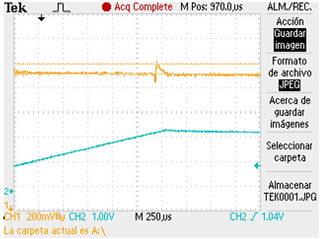
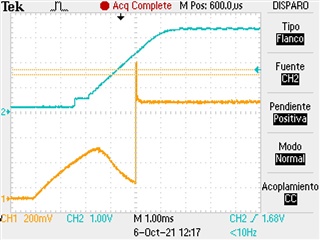
    Blue ==> VIN, EN (10kOhm) to DCDC4 (+3.3V)

    Orange ==> VO pin (TPS51200)

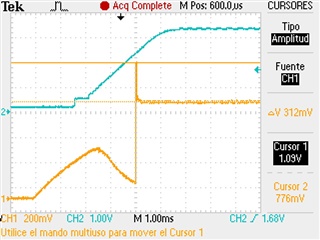
    Blue ==> VIN, EN (0 Ohm) to DCDC4 (+3.3V)

    Orange ==> VO pin (TPS51200)

    The same issue...

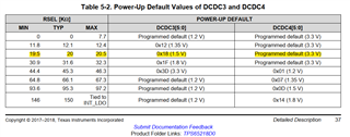
    5) From the default register settings it seems like DCDC3 was configured for 1.2V but your schematic says 1.5V.

    We're using 20kOhm on RSET pin...

    6) DCDC4 inductor: schematic shows 4.7uH but the spec is 1.2uH to 2.2uH. (if you changed the inductor already, please ignore this bullet)

    We have tested values from 1uH to 4.7uH... the same issue...

    7) Does everything works as expected if you replace TPS65218D0 with TPS65218B1?

    Yes. The default value for STRICT bit on TPS65218B1 is '0'. The poweron sequence always ends well.

    Regards.

  • Hi Amilcar,

    Thanks for providing the responses above. It now make sense why you are seeing a voltage on Vtt (TPS51200 VO) before the EN signal (TPS65218 DCDC4) is supplied. Since this was an existing solution that was working with TPS65218B1 (old revision) and external components were adjusted to switch to TPS65218D0 then I would recommend re-programming the STRICT bit with a booster pack (Link:BOOSTXL-TPS65218) before soldering the device into the application board. Once you confirm everything works as expected in the prototype board, then we can look into into the options to receive TPS65218 production devices with a custom NVM config that would include the STRICT bit=0h. 

    Please let me know if you need any support with the re-programing of the STRICT bit using the booster pack.

    As an additional resource, for production programming services you can contact Arrow (TI partnered distributor) and they will support the TPS65218 PMICs with the custom NVM settings (like the TPS65218D0 settings with STRICT bit=0h). Here is the link:  Arrow programming services  

    Thanks,

    Brenda