This thread has been locked.

If you have a related question, please click the "Ask a related question" button in the top right corner. The newly created question will be automatically linked to this question.

UCC256403: About replacement

Part Number: UCC256403
Other Parts Discussed in Thread: UCC256404, UCC256402

Hi team,

I am thinking of replacing UCC256403 with UCC256404B in terms of supplyability.
From the datasheet, there are no major differences other than function, and I thought it would be no problem to replace the circuit as is.
Are there any concerns?
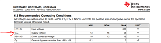
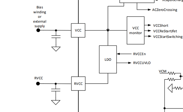
In addition, are there any restrictions on the timing of the VCC input when using High Voltage Start-Up?

Sincerely.
Ryu.

  • Hi Ryu,

    Thanks for reaching out to us.

    1. You can find the main differences between the devices (UCC256403 and UCC256404B) in the following pdf:

     1680.UCC25640x Selection Guide.pdf

    2. There are no restrictions on the timing of the VCC input when using high voltage startup for UCC256404B. Both the devices starts switching when BLK voltage is more than the threshold voltage. You can refer following timing diagrams for comparison:

    3. As both devices has similar pin configurations, you can replace the 403 with 404B. However, since some of the threshold voltages (for ex: BLK pin voltage) of the both the devices are different, you might need to tune the circuitry (resistor values) around the 404B IC.

    You can compare these difference in these threshold voltages in the below picture.

    I hope these comments clarified your questions. Please let me know if you have any further questions.

    Regards

    Manikanta P

  • Hi Manikanta,

    Thank you for your reply.
    That was very helpful.
    I'll contact you if I have any more questions.

    Sincerely.
    Ryu.

  • Hi Manikanta,

    I have an additional question.
    Is it possible to use the same VCC supply that was used in the UCC256403 through the diode?
    Is there any problem in that case?
    Also, the value of IFB is different between UCC256403 and UCC256404B, does this cause any problem?

    Sincerely.
    Ryu.

  • Hi Ryu,

    My apologies for my previous comments. Today I spoke with one of the system engineer. He said that instead of choosing UCC256404, UCC256402 is recommended to replace the UCC256403 with minimal circuit changes.

      404 403 402
    Initial voltage required 26V 10.9V 26V
    AC zero cross detection treats as a fault No problem No problem

    As you can see in the above table, In case of UCC256404, VCC voltage need to rise to 26V. That is when RVCC (supply to the gate driver and PFC controller) will be enabled. So, If you use the same supply as UCC256403 where there is a fixed bias supply voltage of 10.9V, UCC256404 does not even start. Also, since 404 has x-cap discharge feature, if there is no AC zero cross detected at HV pin, it will consider input voltage as removed whereas 402 should be okay with that since it does not have x-cap discharge feature. In other words, 404 has to have rectified AC voltage at HV pin otherwise it goes into fault mode.

    Also for 402, you can use the similar VCC circuit as 403 except that VCC voltage should be 26V.

    Regarding IFB current, you just need to pick the right optocoupler so that it won't be saturated.

    I hope these comments clarifies your questions.

    Regards

    Manikanta P

  • Hi Manikanta,

    Thank you for your reply.
    Only UCC256404B can be used due to the effects of supplyability.
    AC voltage is connected in both cases.
    I understand that VCC is not affected by the external power supply until it drops below the power supply connected to VCC after it reaches 26V by High Voltage Start-Up.
    Isn't that right?
    The point is, can I continue to connect VCC to the external power supply that was connected at the time of "UCC256403"?

    Sincerely.
    Ryu.

  • Hi Ryu,

    In case of UCC256404B, you can connect the external supply along with the HV start-up circuit as below. 

    Here Vdc can be 15V. As Vdc increases more than 15V, there will be a increase in power dissipation.

    If you use the similar voltage as 303 which is 10.9V, then there will be a reduction in RVCC pin voltage which is nothing but gate drive voltage. Reduction in RVCC increases the  Rdson of the MOSFET which increases the conduction loss.

    I understand that VCC is not affected by the external power supply until it drops below the power supply connected to VCC after it reaches 26V by High Voltage Start-Up

    Yes, That's correct. Vdc charges the VCC capacitor only when VCC voltage is less than Vdc.

    I hope this clarifies your question.

    Regards

    Manikanta P

  • Hi Manikanta,

    Thank you for your reply.
    I understand better now.
    Can you tell me a little more about this?
    Does it mean that I should not input more than 15V?
    Or does it just increase the power loss?
    If so, what is the best voltage to use?

    Sincerely.
    Ryu.

  • Hi Ryu,

    Here Vdc can be anywhere between 13 to 26V. You can see these values in the recommended operating conditions of the datasheet.

    So , the recommended value for Vdc is 15V. 

    If you increase more than 15V, it's just that power dissipation in the IC increases. This is because there is a LDO inside the IC trying to regulate RVCC voltage at 13V.

    Please let me know if you have any further questions.

    Regards

    Manikanta P

  • Hi Manikanta,

    Thank you for your reply.
    I was able to answer my customer.
    I'll contact you if I have any more questions.

    Sincerely.
    Ryu.

  • Sure. Thank you.

    Regards

    Manikanta P