This thread has been locked.

If you have a related question, please click the "Ask a related question" button in the top right corner. The newly created question will be automatically linked to this question.

LM5163: Ripple under different loads

Part Number: LM5163

Hi,

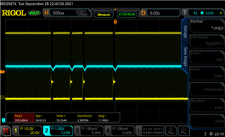
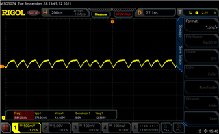
I'm using the LM5163DDAR as a DC/DC converter from an unregulated input voltage to +12VDC. When the output is

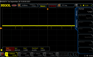
only loaded with around 150mA, I get this high ripple voltage (400mV) and I think this comes from the fact, that the LM5163 goes

into the discontinous regulator mode, since the load is too low. Am I right with this assumption?

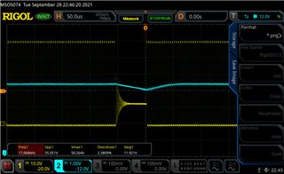
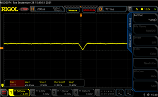
When I then increase the load to around 250mA, the voltage becomes very stable and nearly no ripple, except there

is every few ms a smaller voltage dip of around 400mA and this looks like, the LM5163 switches between continous and 

disconitnous mode.

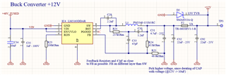
My schematics and layout looks like this, where I used webench for the design and component choice:

(C31 and C92 are not assembled at the moment)

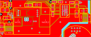
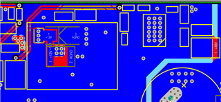
So the layout seems not to be too bad and I think either the output buffering is not enough or the load is too small. What do you think?

  • HI

    can you try to add C92 and in the same time, check the SW waveform vs Vo ripple. it looks like IC's SW have some jitter or dithering which make the output unstable.

    and if output ripple is too large , it will impact the the feedback loop because it will inject the ripple to FB which make the FB ripple phase have lag compare to inductor current ripple. increase the output capacitance may help for reduce this impact.

    Thanks 

  • Hi Daniel,

    I did not add the C92 yet, I need to desolder first one. I already had a 100uF bulk at the output once, this gave no improvement, but I will try with a ceramic one next.

    The measurements looks like this (Yellow is the SW, blue the output after the inductor):

    Sometimes, the converter stops switching, probably a violation of the minimum on-time? How can I compensate for this? Do I need a minimum constant load, for example a resistor or should I change the switching frequency?

    The Dips start, when I increase the input voltage to more than 34VDC. The maximum voltage can reach up to 65VDC, so how should I change the ton time? I think this should be possible by changing the RON resistor, right? But if so, do I need to redesign the inductor, filter and output cap?

  • HI

    100k Ron should be 300Khz frequency, I don't think it will trig min on time.  

    Can you try to change C33 to 0.1uF see any improvement?

    Thanks

  • Hi Daniel,

    I tried to add a 100nF C33, but this seems not to solve the issue. What I can observe is, than when I lincrease the output load, I can also increase the input voltage until the dips start. So at 20V Vin and around 150mA load, I have no dips at all, at 25V, the dips begin to start. When I load the circuit with around 250mA, the dips start at around 35V. 

    The schematics is from webench, designed for 500mA, so at the moment I don't have that much load, so that might be an issue? 

  • About the 0.1uF, I have desoldered the wrong cap at the beginning, so now I replaced C33 and I don't have any dips at all, thanks so far. But is this really a solution or what is the trade of for such a large feedback capacitor? If this is not a solution, how can I find a big enough Cb and why did it not work withwebench in the first place?

  • HI Tschabold

    glad to see it improved. I think it should be the solution.

    As C33 is very close to boot pin, so I think larger C33 will help reduce the dv/dt coupling to FB. I  think layout may also impact to this issue. 

    Thanks

  • Ok, but what I don't understand is, why Webench recommends 47pF, that is way different from 100nF? Might this not increase the settling time and faster voltage transients cannot be handled as fast as with a lower C33? Should I try out for example 100pF?

    Can you tell me, what I should change in my layout? At the moment I cannot see what I'm doing wrong here...

    Kind Regards,

    Sebastian

  • Hi Sebastian, 

    In general I think it is normal to have more output ripple at light load as the part will reduce the switching frequency to save power. 

    0.4V does seem high though. 

    We have a quick start calculator (excel based) that you can use to tune the component values and the ripple injection circuit. You can get it here:

    LM5163-LM5164DESIGN-CALC 

    Can you please enter your operating conditions and try updating the ripple generation components (R21 C30 C33) and see if you get any improvement?

    Regards, 

    Denislav

  • I could solve now the problem, the thing is, the 47pF capacitor was derating at 40V for a 100V version. Since I added a 100pF 100V cap it works fine.