This thread has been locked.

If you have a related question, please click the "Ask a related question" button in the top right corner. The newly created question will be automatically linked to this question.

CSD19532Q5B: Inquiry about using CSD19532Q5B

Part Number: CSD19532Q5B
Other Parts Discussed in Thread: TPS2419

Hello,

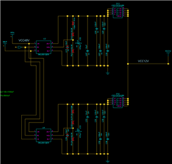
My customer wants to use the two isolated DC/DC outputs by connecting them in common using two CSD19532Q5Bs as shown below.

This is to keep supplying 12V to the other even if one output fails.

Below is the isolated DC/DC datasheet.

PKU5500E-RevH_2020-11-03-080227.pdf

Can you please advise the customer if the CSD19532Q5B is suitable for use?

Thank you.

JH

  • Hello JH,

    Thanks for promoting TI FETs at your customer. The schematic looks OK except the gate and source of each FET are shorted together. The FET will never turn on and the current will be conducted by the body diode. If this is the intent, then the customer can just use schottky diodes with a lower forward drop than the body diode of the FET. There is no power loss advantage using the FETs in this configuration compared to schottky diodes. If the customer wants to reduce the power loss by turning on the FET, then I would recommend using an OR'ing controller to drive the MOSFET gates. TI has many OR'ing controllers that would work in this application such as the TPS2419. How much current does the FET need to conduct? The CSD19532Q5B is a 100V FET and is probably overkill for this application. A 25V or 30V FET should work and will be more cost effective. What is the maximum voltage that can be seen at the output? Are there any transient requirements?

    Best Regards,

    John Wallace

    TI FET Applications

  • Hi JH,

    Following up to see if this has resolved your issue. Please let me know if I can be of any further assistance. If I do not hear back from you in the next day, I will assume your issue is resolved and close this thread.

    Best Regards,

    John