This thread has been locked.

If you have a related question, please click the "Ask a related question" button in the top right corner. The newly created question will be automatically linked to this question.

LM66100: LM66100 CE control pin

Part Number: LM66100

Hi !

I am using the LM66100 in one of my design to enable or disable a 5V net.

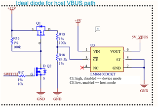
Vin is 5V. ~CE is receiving a signal coming from a 12V rail and divided by a resistive bridge to bring it down to 5.5V

The "12V" signal is enabled depending on a switch control on my system. Therefore ~CE pin is either 0V or 5.5V.

My problem comes when the 5.5V is applied. It should disable the output but it's not. I can still measure the 5V coming out from LM66100.

Am I misinterpreting the usage of this device ?

Thanks for your help

  • Hello Marc,

    You are not misunderstanding the use of the CE pin. When VCE > VIN by 80 mV the device will disable. Do you have scope shots of this event? Scope shots including Vout, Vin, and VCE. 

    You should see Vout = Vin - Vfwd when the device is disabled. 

    Regards,

    Kalin Burnside

  • Marc,

    Before you gather the scope shots I just want to confirm that you're not expecting the output to be zero. This is an ideal diode, not a switch. When the device is disabled it means the PMOS path is disabled, but the body diode forward biased from input to output will still conduct. This means that you should see (input voltage - forward bias voltage) on the output.

    Regards,

    Kalin Burnside

  • Thanks a lot Kalin !

    You were right, I expected it to behave like a switch (silly me). Would it be possible to use 2 LM66100 in a back to back topology ?

    In my case the 5V_VBUS is supposed to be the 5V of a USB port. Depending on the switch value, either my system is providing the 5V (acting as host) or the external device is providing the 5V. In case of an external host failure (if it fails to provide the 5V), without the back to back topology, I guess I could damage the external device by providing even 5V -Vfwd

  • Hello Marc,

    Unfortunately a back to back configuration will not work due to the Vin to Vce comparator. If you have the device set that way the device in the opposite bias can not be enabled.

    Your best bet here is to either use a power mux between your two supplies or to use a load switch in the place of the LM66100. I wouldn't use the LM66100 in an ORing configuration for your setup due to the supplies being at the same voltage level. I've linked our load switch and power mux portfolios below. You can filter by inventory now to see which devices we have in stock that can fit your application. 

    Load Switch Portfolio

    Power Mux Portfolio

    Regards,

    Kalin Burnside

  • Ah yes it makes perfect sense now.

    Thanks a lot for your help Kalin.