This thread has been locked.

If you have a related question, please click the "Ask a related question" button in the top right corner. The newly created question will be automatically linked to this question.

BQ24155: Design review

Part Number: BQ24155

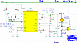
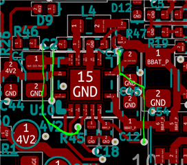
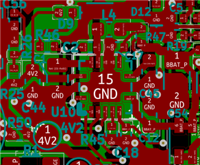
BQ24155RGYR is used to charge a 500mAh Li-po battery. Since this is our latest design we would like to hear from you before sending it to fabrication. Those green colored lines are bottom layer traces connected through vias. Please review this layout and schematic any changes required to better performance please suggest.
Looking forward to your valuable feedbacks.

Thanks,

Ravi

  • HI Ravi,

    I do not see any obvious errors on the schematic or layout.  I noticed that VBUS is 4.2V.  The charger needs 200-300mV headroom to charge so the max controlled charge voltage will be about 4.0V.

    If you are concerned with EMI, then I recommend adding a 0.1uF on PMID in parallel with the 4.7uF and pads for an RC snubber on SW to GND.  The snubber would be a last resort.  The 0.1uF and snubber components should be the closest to IC pins and GND.

    Regards,

    Jeff

  • Hi Jeff, Thanks for your earlier review. 

    You mentioned that BQ24155 needs 200-300mV headroom and for our Vin 4.2V(VBUS), the charge voltage is 4V (VOUT). But, the datasheet says that the Maximum duty cycle can go up to 99.5% I assume that means there shouldn't be any major voltage drop. I'm curious to know how that voltage drop can result in the 200 to 300mV range. Please write us back as earliest possible.

    Regards,

    Ravi

  • Hi Ravi,

    I haven't supported this device and forgot about the high duty cycle.  So, it should work for application.

    Regards,
    Jeff