This thread has been locked.

If you have a related question, please click the "Ask a related question" button in the top right corner. The newly created question will be automatically linked to this question.

TPSM53604: Switched capacitive load causes large output glitch

Part Number: TPSM53604
Other Parts Discussed in Thread: LMZM33604

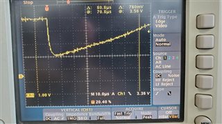
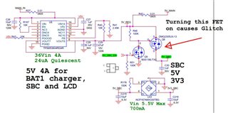
I have a design where this device supplies 5V to my PCBA.  My PCBA has a low current draw sections and a high current draw section.  When I push a button, a P-FET is used to allow power to the primary draw of power (CPU SOM).  When I turn the SOM on the current draw goes from a very low draw to 1-2A but there is a lot of capacitance on the circuit (200uF - probably more counting the SOM capacitors).  I see a glitch on the 5V output to below 2V for a very brief period and that resets everything.

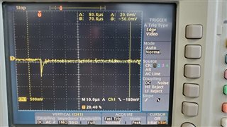
I have removed the SOM and it does the same thing, I think because of the 200+ uF ceramic caps.  As a test I have changed the circuit so I just drive a 2 Ohm resistor and the output is flat and perfect.  It seems like just initially driving the capacitive load causes this glitch.

I have added considerable input / output capacitance to the TPSM53604 but it has no effect when switching the capacitive load, still the glitch.   I am guessing that the device cannot switch from PFM mode to PWM mode fast enough to charge these ceramic caps.  Is there away to force PWM mode before I switch the capacitive load in?

Any other suggestions?

Thanks
Rob

  • Hello Rob, 

    I wonder if your load is tripping the current limit of the device. 

    Could you provide a waveform of the load current when you switch it on and a waveform of the the glitch?

    Could you please also share your schematic for us to review? 

    Thanks, 

    Denislav

  • Hi Denislav,

    I think that is exactly what is happening but it is only 200uF of capacitance.  Just that brief instant of on time causes this module to fail quickly.  An only resistive load causes no issue.


    Attached is a photo of the voltage drop when I switch in the capacitive load, the current profile across a 0.01 Ohm resistor and the schematic of the circuit.

  • Hi Robert, 

    Switching in empty capacitance as a load would present itself as a momentary short circuit on the output. 

    You can try the following:

    1. Add more capacitance on the module output side before the switch. That way you will have larger "reservoir" when you switch in your load and hopefully it will help absorb some of the current draw when you switch in the load. 

    2. Add some current limiting resistance in series with your switch to control the current. 

    3. Switch in the load at time 0 and control the EN of the downstream IC instead, so that the capacitance on the output of the regulator is charged up during the soft start.

    Let us know if any of these provide improvement. 

    Cheers, 
    Denislav

  • Hi Denislav,

    1 - Yep tried that.  Did not seem to help at all.
    2 - Worried that the large current draw through a resistor from the operational SOM and display will weigh heavily on a voltage drop and voltage ripple during operation.  There is a backlight powered display on this line.
    3 - There is not an IC to disable, it is a SOM (System on Module) that is running Android and a very nice graphics display.  There is not an ON/OFF input that will reduce the current to zero or near zero.

    Not sure why this power module does not have an input that does not allow a forced PWM mode.  This is a killer.  I could put a switch in parallel to switch in a 5 Ohm resistor to force the module to turn on but that is kind of crazy to have to do that. 
     

    Thanks for your help.

    Best

    Rob

  • Hi Rob, 

    You mentioned forced PWM mode.
    The LMZM33604 (and LMZ33606 for 6A) have a dedicated MODE pin to run in Auto PFM mode or FPWM mode at light load. There are larger modules though. 

    Can you please confirm the input voltage waveform during this glitch?

    I see that the output capacitor is 47uF 10V rated 1206. What is the DC-bias derating on this capacitor at 5V bias and how much more did you try adding there? I am surprised that adding more capacitance did not help at all. 

    Do you get the same glitch if you pre-load the TPSM device with a resistor prior to switching in the capacitive load?
    I wonder if the glitch partially has to do with the module transitioning from light load (PFM) mode to full load current as the fast load transient comes in.
    Pre-loading the TPSM device output so it is out of light load (PFM) mode when the load transient comes could be a good debugging step to check that. 

    Cheers, 
    Denislav