Hi
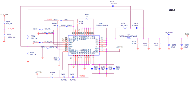
could you help check the TPS53315 schematic as below and any need to adjust
thanks

This thread has been locked.
If you have a related question, please click the "Ask a related question" button in the top right corner. The newly created question will be automatically linked to this question.
Do you have a part number or specs for the 470uF output capacitors.
The RCC circuit around the inductor and the esr of output capacitor must be taken into consideration.
The capacitor's esr will affect the stability and the output voltage level.
The DCAP control uses the output voltage to regulate.
A large ripple voltage on output and the RCC will cause the output voltage offset.
It is not clear on the schematic of the desired output current or switching frequency.
The RF resistor of 187k implies 300kHz. The Rtrip of 44.2k implies the current limit is ~9A. However when I google the inductor part number,
I came across an inductor with 40mOhm resistance and a 10A saturation current and 5.5A temp rise current.
The saturation current is lower than I would expect with that Rtrip setting. Also, the 40mOhm DCR will have high power loss at the higher current.
consider using the webench design on the product folder https://www.ti.com/product/TPS53315#design-development and using components with similar specs.
Hi David
99H18-001382 : POS CAP 6TPE470MAZU 470 uF 6.3V SMD D15E TYPE M SANYO(PANASONIC)
May I ask how much inductor saturation current needs to be greater than the ocp current?
The peak inductor current is Iout + Iripple/2. so Ipeak about ~10.3A, So the minimum saturation current should be greater than 1.2xIpeak.
Using an inductor that has a RDC of 15 mOhm rather than 40 mOhm will boost efficiency >3%.
Since the esr is higher on the Cout, R576, C428 an C434 are optional. Using the ceramic only on the output is required to use the RCC, section 8.2.1.2.3 discusses.