Because of the Thanksgiving holiday in the U.S., TI E2E™ design support forum responses may be delayed from November 25 through December 2. Thank you for your patience.

This thread has been locked.

If you have a related question, please click the "Ask a related question" button in the top right corner. The newly created question will be automatically linked to this question.

TPS7A19: Use of MTTF and FITs during thermal cycling

Part Number: TPS7A19

This is a somewhat generic question but this is a device that I am evaluating.

In my application the output of the TPS7A19 is accessible to the user and may be shorted out, and that short circuit may be left in place indefinitely.  This would cause the regulator to overheat and go into thermal shutdown, where it would cool off, re-enable, and heat up again, and this cycle may go on as long as the system is powered and the short circuit remains.

I know that this is a Bad Thing, but I am trying to understand the expected MTTF or failure rate from this situation.  My question is whether the FITs rate, derated for 175°C (the thermal shutdown threshold) is applicable in this situation.  Using the FITs number, I can propose that, say, 10,000 units are operating in this situation, for 24 hours a day and 365 days.  That's a total of 10000 x 24 x 365 = 87,600,000 device hours.  The MTBF/FIT estimator gives me 0.2 for this part, and the derating tool (temperature change FIT) gives me a FIT of 2590 at 175°C (at 1.0 eV).  Given my device hours, that works out to 87600000 x 2590 / (10^9) = 226 failures over the course of a year.

Is this a valid calculation?  Most datasheets point out that the device should not rely on the thermal protection and this datasheet says that "Continuously running the TPS7A19 device into thermal shutdown degrades device reliability".  But the datasheet does not quantify what that means.  Is my usage of the FITs data a valid way to determine the failure rate of "continuously running the TPS7A19 device into thermal shutdown"?  The datasheet seems to imply that the part will rapidly degrade and fail.  But the FITs calculation implies that, out of 10,000 units, maybe less than 3% would actually fail over the course of an entire year spent at the thermal limit.

This is not to imply that a 3% annual failure rate is acceptable.  This long-term short-circuit scenario will likely be very uncommon.  But I am just trying to figure out if this situation would cause a TPS7A19 to fail very quickly, or perhaps not really at all.

  • Hi David,

    I'm looking at your question and I'll get back to you within the next business day.

    Regards,

    Nick

  • Hi David,

    Your calculation is valid for the HTOL JEDEC specification, except that we normally use the FIT rate with 0.7eV activation energy (and the 0.2 FIT rate is at 0.7eV activation energy). In this case the number of failures in your application would be 87600000 x 151.3 / (10^9) = 13 failures over the course of a year due to high temperature use. Since this is also a relatively high-current application scenario, failures due to electromigration should also be considered. I have reached out to our design team to provide an FIT rate due to electromigration and I will let you know when I have information to share. 

    Regards,

    Nick

  • Hi David,

    Design got back to me. With the following assumptions, the FIT is 14:

    • 1 year approximated to 10k hours
    • 50% of the time the part is in current limit at 150C
    • 50% of the time the part is in thermal shutdown at 105C

    Regards,

    Nick

  • Hi Nick,

    When you wrote "thermal shutdown at 105C", did you mean 175C?  Thermal shutdown is at 175, so the expected behavior is, operating in current limit until the temperature hits 175C, then cooling off to 150C, then back to current limit and heating up again.  If the 105C becomes 175C I think this is correct.  Otherwise can you explain where the 105C comes from?

    Also to confirm - are you saying that the FIT is 14?  Or that the total # of failures is 14?

  • Hi David,

    I believe it was intended to say 105C and not 175C. It was the designer who ran the sims that provided these assumptions. I think the intent was to include the time the LDO spends cooling to a temperature less than when it is running at current limit. I suppose this is a standard way of obtaining the FIT due to electromigration. 

    Yes the FIT due to electromigration is 14, not the total number of failures.

    Regards,

    Nick

  • In that case I'm not sure if the data from that scenario is relevant - the part will cycle between 175 and 150, and will not cool down to 105.  

    The FIT due to electromigration - is that added on top of the FIT due to temperature?  If 151.3 was correct based on the MTBF/FIT tool, is the total failure rate 151.3 + 14 = 165.3?  Or something else?

  • Hi David, 

    Yes these are additional failures and the rates can just be added together. If you would like I can request a new FIT due to electromigration when cycling between 175C and 150C

    Regards,

    Nick

  • Yes please - whatever is needed to get our best estimate of the expected failure rate when cycling between 175C and 150C due to a short circuit.

  • Hi David,

    Please allow some time to get a new FIT number due to electromigration for the following scenario:

    • 1 year approximated to 10k hours
    • 50% of the time the part is in current limit at 175C
    • 50% of the time the part is in thermal shutdown at 150C

    Regards,

    Nick

  • Hi David,

    You were correct when you thought the previous conditions were not representative for this extreme scenario. The FIT is 10e5 with the previously stated conditions in my last comment. At 10k hours, this corresponds to 100% failures over the course of a year operating like this. 

    Regards,

    Nick

  • That's much worse!  But it does make sense.

    Are you able to quantify the MTTF for a single unit operating in this scenario?  Basically, will the average unit fail within minutes?  Or hours?  Or days?  I am working on ways to mitigate the scenario but it would help to know how quickly the device could fail.

  • I'm not sure how we could quantify an MTTF for this scenario. I would expect the device to fail beyond the scale of hours because I have myself done tests where a part is cycling in and out of thermal shutdown overnight and it survived, but beyond that I can't say with certainty how long it would survive these conditions. 

  • Ok thanks.  The idea I have is to monitor the output voltage for a short circuit - basically if the output falls below some relatively low threshold.  If it does I would turn the output off for some amount of time before turning it on again.  It takes several seconds for the part to hit the thermal limit so I should be able to turn it off and let it cool down before that happens.  This is essentially hiccup mode protection, but implemented externally.  Does this sound reasonable?  Have you seen it done this way before, or do you have other recommendations?  I should mention that I have a microcontroller in the system that I can use to implement the protection scheme, it doesn't need to be a fully analog solution.

  • Hey David,

    I think that would greatly reduce the number of failures you actually see because that would be much closer to the scenario that produced an FIT of 14. 

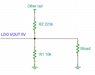
    What about something like the following? If you have another supply rail available you can use it to keep the VOUT at a non-zero (but small) voltage when the device is disabled. When the LDO is on the resistor divider just acts as a small load for both supplies. This would allow you to identify when the short-circuit is removed while the LDO is disabled because the output would sit at 0V when shorted to GND but at some other non-zero voltage when the short-circuit is removed. The tolerance would need to be somewhat tight since you would have to avoid forward biasing the body diode of the pass FET. E.g. if you set the resistor divider to 0.25V it would not forward bias the body diode and you could distinguish between short-circuit and not short-circuit while the LDO is disabled. I tested this using the resistor values below with VOUT = 5V and the other supply at 7V and it worked without issue.

    Regards,

    Nick

  • That's clever!  If the LDO body diode forward biases it would still allow a resistor ladder voltage of Vin + Vf, right?  The input voltage to the LDO is always present so I should be able to set the ladder voltage higher than 0.25V.

    I think that either could work.  If I find that I can turn the LDO on, check Vout, and turn it off, before it gets too hot, then that could be just fine.

  • To be honest I don't remember a whole lot about resistor ladders, but TPS7A19 abs max VOUT is VIN + 0.3V so as long as you follow that there will be no problem.