This thread has been locked.

If you have a related question, please click the "Ask a related question" button in the top right corner. The newly created question will be automatically linked to this question.

ISO5852S: Gate Drive IC failure

Part Number: ISO5852S
Other Parts Discussed in Thread: AMC1302

Hi All,

We are working for VFD 22kW Application. We are using the PIM Module FP150R12KT4 which is seven in one module. Front End Rectifier + Brake Chopper + Three Phase Inverter .

We have validated the drive for 1-2 months of time. On a fine day when we have given three phase input after system got live up for 30 seconds. Device got blown off even before TURN ON the inverter.

We have observed that RPHASE TOP and BOT diode showing as open and Gate Driver IC VCC and VEE showing short with OUTL.

What may be the reasons for the failure of Gate Driver IC ISO5852S-Q1. We are unable to conclude whether IC failure had caused Module Failure or vice versa. 

Attached Gate Driver section for reference
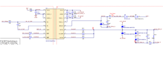
Regards

Manoj.R

  • What may be the reasons for the failure of Gate Driver IC ISO5852S-Q1. We are unable to conclude whether IC failure had caused Module Failure or vice versa. 

    Manoj, 

    What other components were damaged. Both IGBTs?

    Best

    Dimitri

  • Back to back zener diodes in gate emitter not showing voltage drop , R phase IGBT showing very high resistance and RPhase diodes showing open. And as mentioned gate driver IC is also short

  • Manoj, 

    This issue is systemic, it is very unlikely to have been caused by the gate driver. The failure mode would turn the driver off. 

    This failure of the IC is often caused by electrical over stress / overvoltage, which also would explain why zeners in the gate path are damaged. 

    Best

    Dimitri

  • Dimitri,

    Thanks for the explanation. What are all the probable causes of failure of Gate Driver IC. Because as explained before TURN ON of Inverter we have experienced the failure.

    Is there any means to  do some experiments for failure analysis of Gate Driver IC. 

    Regards

    Manoj.R

  • Manoj, 

    Is this issue reproducible or is this a one-off failure?

    For next test, i would replace the damaged components in the Rphase on the SAME board and retest. 

    If youre saying the IGBT on that phase are getting damaged, I don't think we should be looking at the gate driver as the root cause but rather system-level issue. 

    The only other thing i could think of that could damage the zeners before the inverter is turned on is if somehow the driver output was High at turn-off at a time when VCC2 was not properly regulated and higher than 16-17V which would forward bias the zeners and overheat them. But, i dont think this would cause IGBT failure. And it would have to be very high voltage to damage the IC in this way. 

    Judging from OUTL being damaged, I have suspicion that there was EOS on that pin. There may have been a high voltage on that pin which destroyed the zeners and damaged the internal pulldown FET, shorting it to VEE. If no other driver turned on at this time, i suggest to look at rphase VCE during turn-on, VCC2 during turn on, and probe the rphase

    Other than this, do you see any other shorts / external components failures? In particularly I'm asking about DESAT circuit which connects to drain and thus, high voltage. 

    How is VCC2 regulated? Early on, is there potential for it to be unregulated and exceed AbsMax of the gate driver?

    Chasing a one-off issue like this is very difficult to establish a root cause or solution.

    Best

    DImitri

  • Hi Dimitri,

    Thanks for detailed explanation. 

    Could you please clarify on EOS . I didn't understand the same. 

    DESAT diodes which are connected to DC+ shows diode drop and thus fine.

    The VCC2 and VEE2 are regulated with the help of fly back converter.

    And we are using shunt current approach to sense the line currents. The power supply is derived from VCC2 of TOP IGBT's respective phases.

    We are able to see Gate Driver IC , AMC1302 for current sensing , Zener diodes and the IGBT's got damaged.  

    Please note we have validated the converter for the specifications 1-2 months of time. On a fine day after charging before switching ON the inverter the failure is observed. 

    Regards

    Manoj.R

  • Manoj, 

    Could you please clarify on EOS . I didn't understand the same. 

    It means electrical overstress, this can include overvoltage (e.g. applying 1kV directly to device). 

    If the iso-amplifier is failing too, we need to look at the system cause. 

    The IGBTs will not fail unless both are falsely turned on at the same time for a long duration, or if there they are operated some otherway outside their SOAs. 

    I think this is the key point we need to consider, especially since we see the isolated amplifier failing too. I dont see its circuit but this amplifier shouldn't be failing if the gate driver does. 

    At this point, I am not really able to provide support beyond my recommendations in my  last reply. I had some testing suggestions I think would be good to attempt. 

    Best

    Dimitri