This thread has been locked.

If you have a related question, please click the "Ask a related question" button in the top right corner. The newly created question will be automatically linked to this question.

BQ51050B: Design help & review

Part Number: BQ51050B
Other Parts Discussed in Thread: BQ51013A, BQ51013B

Hi.

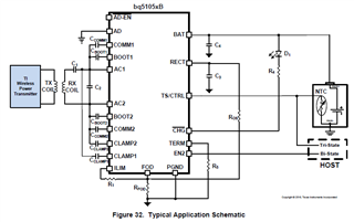
We want to develop some products with wireless charging and we plan to use BQ51050B on them, but I need help for design.

First I will develop a schematic and a simple board to test the circuit alone before integrating this circuit in the products.

My initial doubt is: how to determine the values of RFOD and ROS? Or how to calculate/estimate their initial values for a prototype? Are there suggested values? I can't find on the datasheet the method to calculate them.

Because I will calculate R1 only after RFOD value is defined.

Regards.

  • Hi Jeferson,

    A good starting point for the RFOD resistor is 200 Ohm, from there FOD calibration can be done using the FOD calibration tool to adjust the value. 

    Best Regards,

    Anthony Pham

  • Hi Anthony, thanks.

    And how to determine the initial value (for a prototype) of resistor ROS? (The resistor that is connected between FOD and RECT pins) ?

    EDIT: I saw later that BQ51013A don't show ROS in its schematic and that the datasheet says to connect a 140 ohms resistor from FOD pin to GND. Is BQ51013A easier to certicate regarding FOD? Could you clariry about the certification regarding the different IC models BQ510xx?

    Regards.

  • Hi Jeferson,

    The BQ51013A does not have FOD and cannot be Qi certified. 

    For the BQ51013B, the ROS resistor is 20kOhm. 

    Best Regards,

    Anthony Pham

  • Hello Anthony, thanks.

    I almost finished the schematic of my test board for BQ51013B/51050B, I will share soon.

    This is only a test board, not a product board, its just a simple test with the ICs, to generate a 5V rail with 51013B or charge a Li-ion battery with BQ51050B, via wireless power only. I just want to see the circuit working in free-space.

    I have defined the receiver coil for the first attempt, WR221230-36M8-G from TDK, and I am ready to calculate the capacitors, but according to the datasheet there is two measurements of the inductance of the receiver coil, that are Ls and Ls'. Ls is the free-space inductance, and this value is shown in the datasheet of WR221230-36M8-G, 27.9uH @ 100KHz @ 1Vrms. I have understood that Ls' is the same measurement done being the transmitter and receiver coils with a 3.4mm spacer between them and being the receiver coil installed at its position in the actual product. Am I wrong?
    The thing is that I will not be able to make the measurement of Ls' because we don't have the product yet, nor the spacer to say. As I said, we just want to make free-space tests firstly. Then I ask, in this case, can I consider Ls' equal to Ls if the tests are free-space only? What can I do?

    Regards.

  • Hi Jeferson,

    Looking forward to the finished schematic. You are correct about the Ls and Ls' measurement. For a test board, it's fine to use the an Ls' value that is the same as the Ls that is measured. Some adjustments can be made afterwards if you find the Ls' to be different with the testboard.

    Best Regards,

    Anthony Pham

  • PCB-WC1-A_sch_rev_A.pdf

    Hi Anthony, thanks.

    Here is the current schematic.
    I have not done the calculations yet, this is the next step. I need to calculate the current limit (ILIM) resistor, and the capacitors connected to the receiver coil (C1 and C2) and find a good combination for the 3 capacitors in parallel.

    Do you have any observation?

    Regards.

  • PCB-WC1-A_sch_rev_B.pdf

    Hi Anthony, here is my final schematic, I will start the PCB layout based on this. Do you have any observation?

    Here are the calculations.

    ***** Calculations for BQ51013B *****

    Rilim = Kimax / Imax
    Ilim = 1.2 * Imax = Kilim / Rilim
    Rilim = R1 + Rfod

    - IMAX is the expected maximum output current during normal operation.
    - IILIM is the hardware over current limit.

    So Rilim = Kimax / Imax, and Kimax = 262 (A-ohm)
    Rilim = Kimax / 0.25
    Rilim = 1048 Ohms

    R1 = Rilim - Rfod
    R1 = 1048 - 197
    R1 = 851 Ohms
    R1 commercial = 820 Ohms (No need for precision)

    - Recalculating for the commercial value:

    Rilim = Kimax / Imax
    Imax = Kimax / Rilim

    Rilim = 197 + 820 = 1017 Ohms
    Imax = Kimax / Rilim
    Imax = 262 / 1017
    Imax = 257mA (ok)

    For BQ51050B:
    Ibulk = Kilim / Rilim
    Ibulk = 314 / 1017
    Ibulk = 308mA (ok)

    *******************************************************

    C1 = 1 / [ (fs*2*pi)^2 * Ls' ]
    C2 = 1 / [ (fd*2*pi)^2 * Ls - (1/C1) ]
    -fs is 100Khz
    -fd is 1MHz
    Q = (2*pi*fd*Ls) / R
    -Q must be greater than 77
    -R is the DC resistance of the receiver coil.

    * RECEIVER COIL = WR221230-36M8-G (TDK)
    - L = 27.9uH @ 100KHz @ 1Vrms
    - DCR max @ 25 degree C = 1.21 Ohms

    C1 = 1 / [ (fs*2*pi)^2 * Ls' ]
    C1 = ( ( 1 / ( (100000*2*3.1415)^2 * (27.9*10^-6) ) ) * 10^9 ) [nF]
    C1 = 90.794nF

    C1 commercial = 82nF + 10nF
    C1 commercial = 92nF

    C2 = 1 / [ (fd*2*pi)^2 * Ls - (1/C1) ]
    C2 = ( 1 / ( (1000000*2*3.1415)^2 * (27.9*10^-6) - (1/(92*10^-9)) ) * 10^9 ) [nF]
    C2 = 0.9169nF
    C2 commercial = 820pF + 100pF
    C2 commercial = 920pF (0.92nF)

    Q = (2*pi*fd*Ls) / R
    Q = ( 2 * 3.1415 * 1000000 * (27.9*10^-6) ) / 1.21
    Q = 144 (ok, it must be greater than 77)

    *******************************************************

    Do you have observations?

    Regards.

  • Hi Anthony.

    I have finished the initial PCB layout. I am sharing here the updated schematic (I just changed the identifier of some components), and I am sharing here the Altium PCB file and the Gerber files.
    The identifiers of the components shown in the PDF below match the identifiers of the components of the PCB below.

    Could you check the layout?

    Regards.

    PCB-WC1-A_sch_rev_C.pdf

    PCB-WC1-A_01.PcbDoc

    pcb-wc1-a_01_Gerbers.zip

  • Hi Jeferson,

    I'll take a look at the calculations and the provided pcb files and try and get back to you asap.

    Best Regards,

    Anthony Pham

  • Hi Jeferson,

    The layout looks good and I do believe the schematic also looks good. If I did miss anything, please check out the following FAQ Schematic checklist.

    https://e2e.ti.com/support/power-management-group/power-management/f/power-management-forum/925464/faq-schematic-checklist-for-wireless-power-rx/3419086#3419086

    Best Regards,

    Anthony Pham