A related question is a question created from another question. When the related question is created, it will be automatically linked to the original question.
If you have a related question, please click the "Ask a related question" button in the top right corner. The newly created question will be automatically linked to this question.
[FAQ] UCC21520: How can I use an ENable pin as a DISable and vise versa?
Dual channel gate drivers generally comewith either an Enable pin, or a Disable pin. While some designers prefer one option over the other, it can be desirable to design circuits that can utilize both drivers with Enable, and those with Disable (For example, UCC21521 with EN, and UCC21520 with DIS). Such flexibility allows for easy multi-sourcing of driver ICs. While one way to allow such a swap is to reprogram the controller to invert the control signal going to this pin, this is not always an option. Instead it is preferable to to add an inverting circuit to the control pin, removing the need for a control change. This FAQ presents one method to allow swapping of EN and DIS devices simply by choosing which external components to populate.
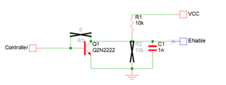
Converting DISable to ENable
In order to allow easy swapping of Enable and Disable devices, a designer can include external components for both configurations, choosing which devices to populate based on the driver currently in use.
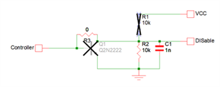
One such circuit is shown in Figure1 and Figure2, with the first figure showing which components to populate for an Enable driver, and the second showing which to populate for a Disable driver.
This solution allows maximumflexibilitywith minimal changes, allowing easy second sourcing in a market with tight supply . When implementing a circuit such as this it is important to choose a transistor based on the voltage of the control signal, the VCC voltage, and the propagation speed needed.