This thread has been locked.

If you have a related question, please click the "Ask a related question" button in the top right corner. The newly created question will be automatically linked to this question.

UCC24612: Strange gate waveform in LLC application

Part Number: UCC24612
Other Parts Discussed in Thread: UCC256303,

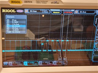
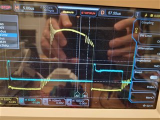
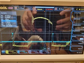
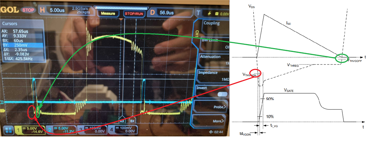
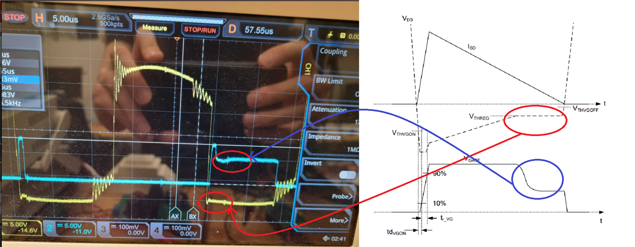
Hello. I'm trying to make an LLC converter with the UCC256303 and two UCC2416-2 on the secondary side. My circuit looks similar to the UCC256303 eval-board except that I have synchronous rectification. The circuit is starting up fine and I'm able to load it a little bit (but poor efficiency so far). One of my UCC24612-2 starts to behave in a strange way when I increase the load (to around 50W) and I can hear noise from my circuit. The gate drive from the misbehaving UCC24612-2 looks like the attached figure. The gate pulses become quite wide, and I can't understand how this can happen. As long as I stay at lower loads, the gate pulses look fine.

Probably my LLC circuit is causing the problems? Can you think of any reason why the UCC24612-2 would behave like this?

  • Hi, Niclas:

    Thanks for asking. You mentioned that one of UCC24612-2 has this phenomenon. May I know if another UCC24612-2 works normally?

    Snice the driver signal of UCC24612-2 is determined by VDS voltage, which is shown on page 14 in datasheet, I would like to suggest you to check the VDS waveform at this condition. The driver signal might be caused by unexpected VDS ringing.  

    By the way, would you please share your output output/power for reference?

    Based on the waveform, the fs seems around 42.5kHz. Would you please check if LLC still works in burst mode?

    Thanks.

    Regards,

    Wesley

  • Hello. Here is the drain of the MOSFET in question (yellow). Blue is the gate of the mosfet. There is definately ringing going on.

    But the gate problem doesn't happen at lower loads, and it looks like this:

    I can't see any difference between the two drain voltage waveforms.

    My goal is to make it work at 300W. Right now I can load up to around 50W before this behaviour begins. I don't think it's in burst mode but I have to check again.

  • The other active rectifier works fine; it doesn't have the same problem. I have also changed the IC to see if the component was damaged. No change. 

  • Hi, Nicals:

    It seems the VDS signal has lots of noise to influence SR control signal. 

    The waveform you shared is as below. As you can see, the UCC24612's DRV on when VDS drops lower than Vth(ON), and then DRV off by an unknown spike. (The figure shows below right is on page 14 in datasheet. The current shape is based on flyback but I thought it is still okay to explain the operation principle.)

    Another waveform with wider pulse with as below, I thought it still meet the UCC24612 still meets its operation principle. 

    As you can see.  VDS drops below Vth(on), and it has less noise than other switching cycle.  and then once VDS increases to VTHREG, DRV signal decreases to regulate VDS voltage to extend DRV pulse to gain efficiency. 

    Based on the waveform you shared, if 

    1. LLC operation is stable. 

    2. Only one UCC24612 at specific location has this phenomenon. It seems it is caused by unexpected noise on VDS signal. 

    I would assume the longer pulse should be correct one. the others pulse is turned off by the noise in green cycle. 

    I would suggest you to check your layout trace to see if it follows UCC24612's layout rule in datasheet.  It is helpful to fix this issue. 

    Regards, 

    Wesley