This thread has been locked.

If you have a related question, please click the "Ask a related question" button in the top right corner. The newly created question will be automatically linked to this question.

TPS7A78EVM-011: High power consumption at no load

Part Number: TPS7A78EVM-011

Hi Team,

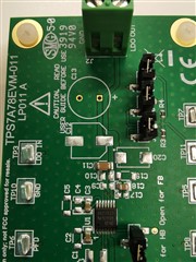
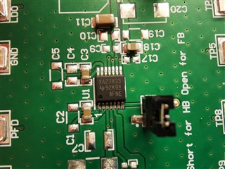
Our customer bought TPS7A78EVM-011 evaluation module and noticed that at 230Vrms input voltage and no load, the power consumption is 6.9W. Table 2 of the user's guide states that the Pstandby is 104mW when the R6 and R7 are shorted. The customer shorted R6 and connected a jumper at J5 connector to short R7 but the power consumption is still the same, 6.9W. Upon checking the top mark of the device, it is different from the one stated in the datasheet (S7A7833) as well as the part marking lookup tool. The top mark on the actual device is XA27833 as shown in the images below. Can you please confirm if it is an original TI device or an imitation? Is the device defective?


Regards,

Danilo

  • Hi Danilo,

    I can confirm that the IC is a TI part and the markings are correct.  I am reviewing the customers other question and will reply within 3 business days.

    Thanks,

    Stephen

  • Hi Stephen,

    Thank you for the confirmation that the IC in the evaluation module is a TI device. Looking forward to the result of your investigation.

    Regards,

    Danilo

  • No problem Danilo, I will reply back when I have additional information to share.

    Thanks,

    Stephen

  • Hi Danilo,

    Please confirm from the customer that they have made no additional modifications beyond the listed mods?  This way if I need to make similar measurements, I will know the setup is the same.  What frequency are they operating at?

    I believe the customer may need to adjust the series Cs and Rs components for their application.  They may be seeing an increase in power consumption at these elevated input voltage levels due to the shunting events.  The EVM was designed for Vac = 120VAC at 60Hz but if the customer increases this voltage then Cs and Rs would need to be modified. I would have them review section 8.1.5 in the datasheet, which may help.

    Can the customer test at Vac = 120V, 60 Hz to confirm they are measuring 104mW?

    If they are measuring high power dissipation at Vac =120VAC, 60Hz then they should review their EVM for any signs of arcing or damaged components that may inadvertently cause a lower impedance to form across the input supply.  The board will want to be clean and free of flux residue from any rework to prevent any arcing paths from forming.

    Thanks,

    Stephen

  • Hi Stephen,

    We have received this feedback from our customer,

    I confirm that the PCB is cleany without any signs of flux. We have not signs of arcing or damaged components. We are working at 230Vac at 50Hz, the standard AC network in Spain. We have not now a power supply that could generate 120Vac at 60Hz for the moment.
    Considering chapter 8.1.5 (TPS7A28 datasheet), it is:
    Ishunt = Vac (MAX) / XCs = Vac (max) × 2 × π × ƒ × Cs
    The EVM has a Cs of 470nF. Using a Vac=230Vrms and f=50Hz, Ishunt of 0,033A= 33mA. We measure 31mA RMS AC (similar), although the frequency of the shunt activity is uncorrelated to the AC input freq.
    For a reference value of Vac=120Vrms and f= 60Hz, the theoretical Ishunt is 0,0213A= 21,3mA RMS, quite higher for having 104mW of standby. What frequency should we consider without load? Is Vac in the formula the network Vac or the voltage between AC+/AC- pins? Please, may you share other measurements?

    Regards,

    Danilo

  • Hi Danilo,

    The frequency in equation 1 is 50 Hz for full bridge operation, and 25 Hz for half bridge operation.  The Vac is the AC supply voltage or 240Vrms.  An example that walks through this from the datasheet is given in section 8.2.2.3.1. 

    What measurements would the customer like me to take?  I will go into the lab tomorrow to locate an EVM and set up a test bench.  If we do not have an EVM readily available, it usually takes 5 business days to ship one to us. 

    Thanks,

    Stephen

  • Hi Stephen,

    According to our customer,

    Till now I have tested different values of C15 in the EVM, always measuring the input current of the EVM with Iout= 0. For a C15= 220nF the input current is 15mA and for a C15= 100nF is 7.6mA.
    My question is what topology or combination of the EVM's components may we use to get a standby power of 104mW at 230Vac input.

    Regards,

    Danilo

  • Hi Stephen,

    Here is an additional information from our customer,

    The target would be at least to know the minimum limit that we can get for standby power at 230Vac/50Hz. This is the most typical network in Europe.

    Regards,

    Danilo

  • Hi Danilo,

    I just received your response.  Please allow 2 business days for a reply.

    Thanks,

    Stephen