This thread has been locked.

If you have a related question, please click the "Ask a related question" button in the top right corner. The newly created question will be automatically linked to this question.

TPS56121: Cold Start-up Failure

Part Number: TPS56121
Other Parts Discussed in Thread: TPS56221,

Hi TI Team,

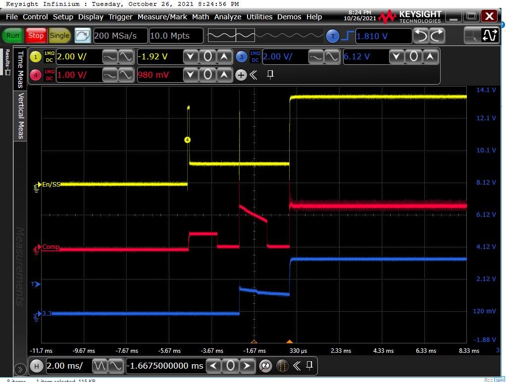
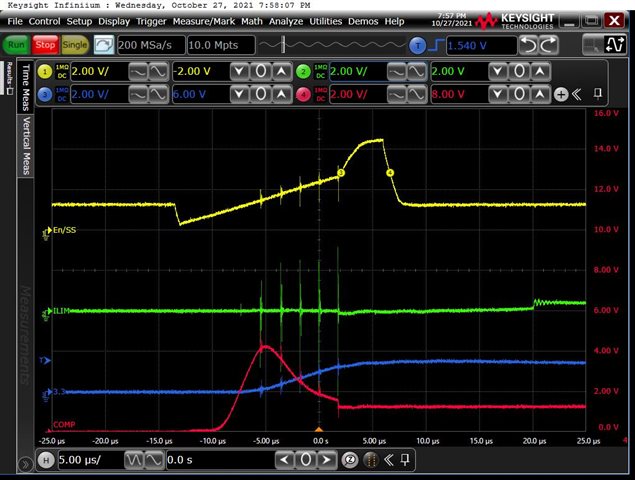
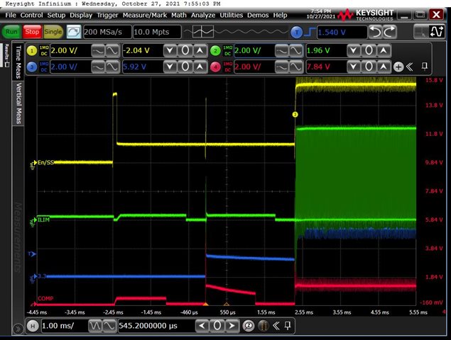
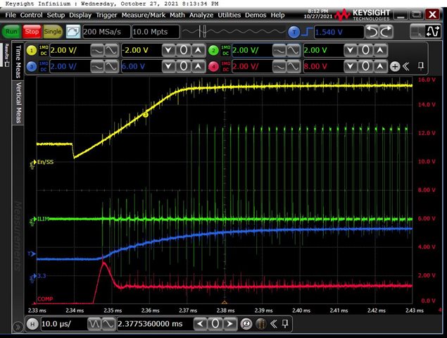
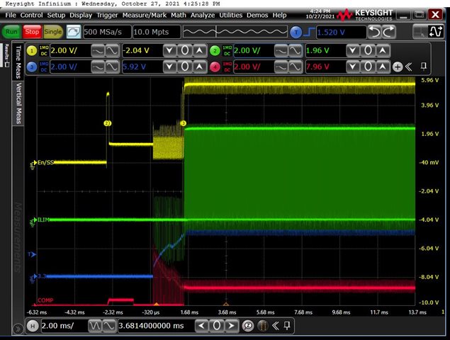
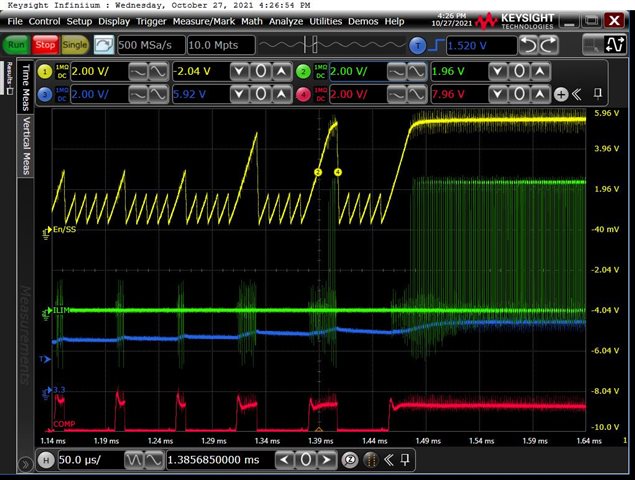
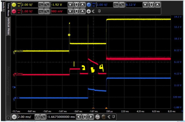
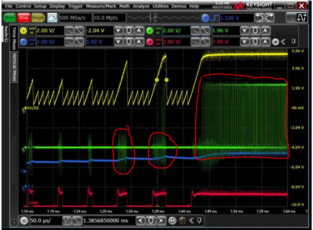
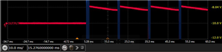
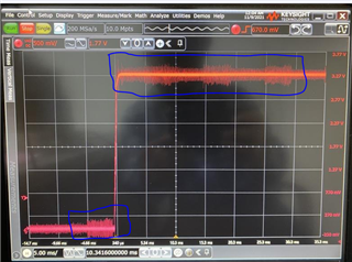
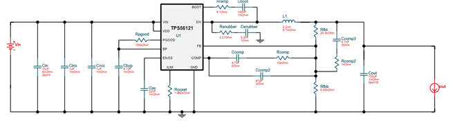
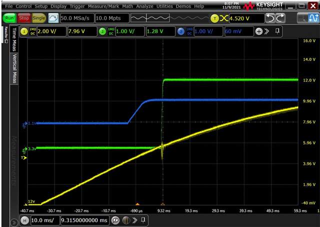
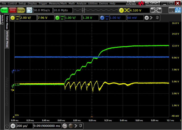
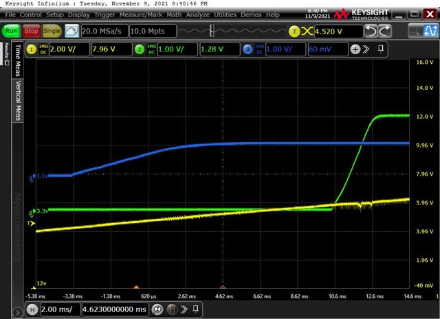
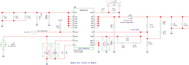
Like similar case we kept our product turn-off for more than 1 hours (we called it as Cold start), we are using TPS56121DQPR to generate 3.3V from 12V input, Problem occurs when we use 6.8nF as soft-start capacitor and 1.21K as RIlim (Current limiting resistor), we observed 3.3V is not generating, it is showing 1V in DMM. we had tried with different soft start capacitor value and current limiting resistor like 1.) 33nF and 1.21K.  2.) 33nF and 2.21K. 3.) 6.8nF & No current limiting resistor.  4.) No soft-start capacitor and 1.21K as current limiting resistor. With above 4 combinations we don't find any issue of cold-start but why the combination of 6.8nF and 1.12K getting failure in cold-start. In our design this 3.3V rail is going to so many devices and due to this the accumulation of total capacitance on output of the regulator becomes around 1700uF.  Our design in the below image:

Early response would be quite appreciating.

Thanks

  • Schematic:  the short soft start time, current limit threshold and large Cout combine such that the OC is triggered during start up.

    If 3 OC events are triggered, the device hiccups and restarts. 

    Case 1   The larger value Css extends the soft start time lowering the peak inductor current during start up.   OC is not tripped. 

    Case 2   Same as Case 1 and  The  larger value Rtrip increases the OC trip point and the device does not trip OC during startup.  


    Case 3   No Rtrip, if trip voltage is 300mV during startup, OC is disabled.     OC is not trigger during startup. 

    Case 4.  No Css, and Rtrip of 1.12k.   Not clear why this does not trip OC.    There is a calibration cycle during start up and maybe the latched OC threshold is different on case 4 vs the schematic case.         Probe the SS/ENA  and ILIM during start up for case 4 and schematic case. 

  • Hi David,

    I was forgot to mention the temperature at which we observe the problem, that is -40DegC we kept our product turn-off at this temperature.

    Thanks,

    Girish

  • Hi David,

    Thanks for the reply!

    As per Schematic there is no Soft start capacitor and Rtrip mounted. So in this particular case OC event may not trigger but what about the behaviour of soft start? like i have taken waveform for the schematic case (NO Css & NO Rtrip) shown below:


    As per Case 4 i have taken waveforms, shown below:

    Please advice: I am thinking to mount 33nF on Css and no Rtrip, No Rtrip means no OC event occurs, Is it right?

    Thanks,

    Girish Singh

  • You should mount a 33nF Css to minimize inrush currents and mount Rtrip to set an overcurrent threshold.

    Set the Css and Rtrip to not trigger OC during startup or cause the input voltage to droop below uvlo


    Image 5 and 6 (no Css and Rtrip=1.12k)

    Image 5 shows the device powering up and Image 6 shows powering and tripping OC (4 restart cycles).

    See 7.3.5 of datasheet on soft start cycles during after OC.

  • Hi David, thanks to revert, what about image 1, Is it ok? Because there is something happening with enable as it is not look like good one.

    2nd thing how do you know in image 6 there is how many times OC triggering happen and how many times it gets restarted?

    I have simulated the design in TI web bench keeping Compensation circuit same as in schematic with the output capacitance of 2mF but the result shown phase margin is too low about -13.61 Degree, will this parameter can be dangerous to the system? or what will be the consequences?

    BTW in another case i am keeping compensation circuit components value in such a way to manage phase margin above 45 Degree (In my case it is 56 Degree)

    and selecting soft-start capacitor of 33nF and Rtrip as 2K (set max OC threshold 20A) will it be fine to go with it?

    Pls suggest as i need to close this activity and based on this activity i have to recommend the change in design to our production house.

    Thanks

  • Image 1 shows the powering up and shutting off and starting again.

    Comp waveform 1:   Calibration to determine switching frequency

    Comp waveform 2:   Comp pin discharges before switching.

    Comp waveform 3:    Comp rises so the device switches, device shuts down

    (I suspect VIN uvlo from large inrush current, drooping the input voltage)

    device repeats calibration.

    Comp waveform 4: Comp pin discharges before device switching again.

    on second start the inrush current is lower and the device 

    Adding Css and Rtrip should mitigate issue

    Image 6.   

    The device starts up and trips OC and the 4 ss cycles is a feature of OC trigger.  On the 5th, the device attempts restart.

    Since the device has no load current, the output voltage remains pre-biased and eventually the output reaches regulation. 

    Also You should test with a load during start up.    Css and Rtrip will mitigate. 

    A stable a design is a must, poor transient response, inconsistent ripple voltage are consequences.

    selecting soft-start capacitor of 33nF and Rtrip as 2K (set max OC threshold 20A) will it be fine to go with it?

    Yes,  the power stage is designs for 25A.  see TPS56221

  • "Image 6" waveform captured during the load condition, how would you say device has no load current?, these above waveforms are captured with load and in start-up condition.

    I would like to have some clear picture on my doubt on the below given image with highlighted section, what actually happening in this particular section?

    Thanks in advance

  • Hi Girish

    David is looking into this and will feedback to you soon.

    BR

    Ruby

  • The circled waveforms is the device switching to bring output upto regulation.  During the startup the low side fet does not sink current on tps56121. 

    The output can only be discharged by the load current. 

    The output voltage does not droop much during the two circled switching intervals.   The load current is closer to no load than to full load. 

    Once the device reaches regulation the device can sink current, hence the continuous switching. 

    Since the previous issue of starting up is related to the current limit, soft start and large Cout, test the seleccted soft start time and rtrip with the maximum expected current during startup to ensure no issues.  

  • Hi David,

    1. During the review of design i found the Output inductor value is not appropriate as per TI web-bench as well as datasheet, for 15A output load design, we should have to keep inductor value around 1.5uH. Just a question what would be wrong if we use  0.46uH of output inductor with 10A load current and 2mF of total Cout? other than noisy output.

    Three more things:

    2. When i try to change resistor value at boot pin in web-bench it doesn't allow me to change value to 5.1Ohm but as per datasheet 5.1Ohm can be connected at boot pin.

    3. When i try to get design with the parameter selection shown in given below "Image 1" using TI web-bench it shows me result as shown in "Image 2" attached below

    Image 1:

    Image 2:

    why this is happening in Web-bench?

    4. As per web-bench and datasheet for 10A design minimum output inductor value should 1.69uH, i used 2.2uH(Coil craft - XAL7070-222ME) with this inductor value output is not properly regulated showing 1.2V. Waveform shown below in "Image 3"

    Image 3:

    but when i use output inductor value of 0.47uH (VISHAY - IHLP2525CZERR47M01), the output was properly regulated to 3.3V

    Is this happen because high inrush current?


    5. 3.3V is noisy shown in "Image 4", i am using components given in schematic "Image 5":

    Image 4:

    Why this is noisy in highlighted zone?

    Image 5:

    Sorry to bother you & Thanks in advance.

  • 1. Using a 0.46uH when 1.5uH is suggested:   The ripple current is larger and the crossover frequency of control loop is higher and will affect the compensation components needed to close the loop.   

    Typically, inductors are sized to have 20% to 40% ripple current (20% to 40% of Io).

    There is higher peak inductor current when using the 0.46uH. 

    3.   go to the TPS56121 product folder  LINK   and initiate the webench design.  

    4.  Measure the inductor current using a current probe.  It looks like the current limit is tripping.

    This image similar to the image 6 above. 

    5.  Use the bandwidth limit on scope and/or use the tip and barrel measurement technique LINK.     

    the ground lead on scope probe can pick up noise from the device or another device switching.  

    You have a very fast start up, the soft start should be longer if a 22nF Css is used. 

    Do you have pcb layout you can share. 

  • Regarding Image 3 in my last post, Output was not regulated to 3.3V with 2.2uH of output inductor and 6.8nF of soft-start cap but when i changed soft-start cap to 22nF the output was properly regulated to 3.3V but seen some irregularity in Vout ramp, shown in below "Image 1a" & "Image 2a" but this irregularity become monotonic when i changed soft-start cap to 33nF, shown in below "Image 3a".

    Yellow Waveform is Vin = 12V

    Green waveform is Vout = 3.3V

    Image 1a:


    Image 2a:

    Image 3a:

    Why this is happened?

    I Think in my fault case, when i cold start-up my DUT the output capacitors are fully empty and they produce a very large inrush current due to this large current a situation might be created like shown in below "Image 4a"

  • Image 1a and 2a shows a soft start time of ~0.5ms.     A 22nF Css should give a longer soft start time of 1.3ms.   

    The inrush current is very high and causing the input voltage to droop.   The input voltage drops and the device stops switching when the input voltage is too low.  The input current goes down to zero when device stops switching and the input voltage rises and device starts switching again.  Repeating the sequence.    Since the output capacitor remains charged, eventually the device reaches regulation. 

      Additionally,  the input voltage source has not reached steady state of 12V when the converter starts switching.   The uvlo on the device is about 4.3V and the output voltage is 3.3V.     The inrush current is larger at lower input voltages such as 5V versus 12V. 

     3a image shows a ~2ms soft start time.   There are some transients on the input voltage waveform when the input voltage is between 5v and 6V.   

    What is the load current during at this time.    Another experiment would be to hold the startup of the converter until the input voltage has settled at 12V. 

    In 4a image, if Cout at zero volts with a fast turn on, if the input voltage drops below the 4.3V the device will stop switching. OC is causing the turn off in 4A. 

    input voltage drop is causing the 2A issue. 

    Another experiment would be to hold the startup of the converter until the input voltage has settled at 12V.   The inrush is will be lower. 

  • What do you mean by this statement?

    "Another experiment would be to hold the startup of the converter until the input voltage has settled at 12V"

    Do i need to increase the softstart time? 

  • Many of the designs I review, enable the converters after the input voltage reaches it final state to avoid start up issues. 

    I think holding the converter off until the input voltage reaches the 12V steady state would minimize the startup issues. 

    The output waveform in image 3a looks good to me.     

    If you have a concern with the input voltage transient,  add an input bulk capacitance of 2x22uF is not much.     The design example in datasheet uses 4x22uF + a 100uF capacitor.