This thread has been locked.

If you have a related question, please click the "Ask a related question" button in the top right corner. The newly created question will be automatically linked to this question.

UCC28780: When UCC28780 enter brown in situation, PWML and RUN become abnomal

Part Number: UCC28780

Hello TI expert:

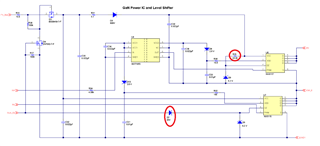
I use UCC28780, Navitas GanIC(NV6115), and MPS SR IC(MP6908A) for active clamp flyback solution.

Follow "Debugging UCC28780 ACF Converter Start-up Issues" document, I have already seen 4 PWML pulse under brown in situation.

Although I have disabled SR controller and changed high side GaN to general diode (change general MOSFET & short Vgs), the abnormal waveform still occur when Vin> brown in voltage.

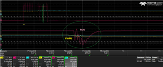
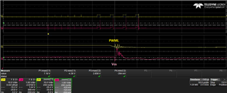
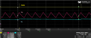
PWML bounce when should be turned off period, it will cause Vcs become higher to reach OPP level. Because PWML will retry after about 1.36s.  

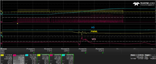
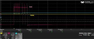
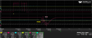
And also I notice RNU pin will drop and bounce when PWML turns off

Do you have any similar experience? Can you give me some suggestions?

Thanks.

  • Hello,

    The RUN pin drop to low level followed by a series PWML pulses is a normal behavior. the PWML bounce after turn off is probably caused by probe . since you can find large noise at turn on and turn off edges.

    May I ask what your output voltage regulation voltage , I afraid the OVP protection been triggered. could you please re-calculate the Rvs1 and Rvs2 to check what is the actual OVP level.

    Thanks.

  • Hello,

    But the RUN pin does not only drop to low level after a series PWML pulses, it drop to low level at each PWML pulse pull low.

    My output voltage is setting to 12V, Turn ratio is Pri:Sec:Aux=24:6:8, Rvs1=48.7K/Rvs2=13.3K, Vovp=14V 

    I think it's not OVP protection, because sometimes I use probe to touch CS pin, Vo will retry several times(8~15 times), then Vo become 12V stability.

    I also added capacitor on CS pin, but it's useless.

  • Hello,

    I don't think the RUN is really pull low but a noise by un-proper detection or poor PCB layout , since if the RUN is really pull low . it will keep at 0V during PWML OFF time , but in your waveforms shows the RUN quickly go high after PWML turn off. Please correctly proper probe the signal by shrink the prober loop, special the GND of prober . in this way , we can clear to identify which is really signal or noise . 

    all of protection are listed in table 2 in datasheet. The ~1.5s restart  protections  are OPP , OCP and OVP , please check it one by one. if OVP is excluded . next is OCP , and OPP .

    Thanks.

  • Hello,

    I am afraid it's real waveform. I already use differential probe and shrink the probe loop.
    I think it's trig OPP, because I measured the waveform as below.

    Do you agree? Then I will check my layout.

    Another question:
    If my transformer with large leakage inductor(Lm=100uH/Lk=10uH), does any problem appear?
    Because when I change the
    transformer with large leakage inductor, whatever I modify component value by "UCC28780 Excel Design Calculator", always only 3 pulse of PWML I can see.

  • Hello,

    Even ACF can recycle the leakage energy, but large leakage inductance will results in lower current drop when low side FET turn off , then higher RMS current at resonant tank and SR FET . and the noise at turn off edge maybe cause fault protection been trigged . we are recommend to limit the leakage inductance.

    Thanks

  • Hello expert:

    Can I ask what function does D7 in reference circuit from UCC28780EVM-002?

    If need more bias current on D6, I think also can put a resistor between VCC and DZ pin like R35.

    Thank you! 

  • Hello,

    Since RUN pin voltage at high level only at burst on interval, during burst off time , RUN is at low level . compare with a resistor connect to VCC , it can save some power loss , so it help for the lower standby power.

    Thanks.