


Other Parts Discussed in Thread: UCC256403
Hi Team,
Could you please let me know more detail on how the burst mode threshold is decided?
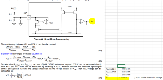
There's a equation (70) and it shows how to calculate VLL. I already know RLLupper and RLLlower in customer board and I get VLL = 7.21V. Is there a way to assume how much of load current makes it exit the burst mode while increasing the load form zero?
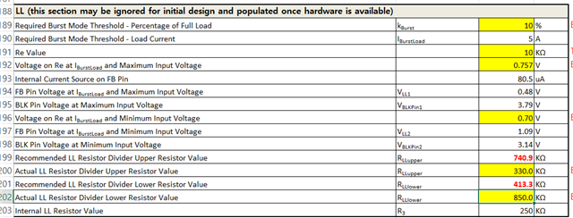
From the excel design sheet, it looks Re (resistor between the feedback optocoupler emitter and ground) should be inserted to calculate the burst mode threshold and target load current, but customer does not have Re on their board.
In addition, I'm actually designing UCC256501. I believe LL/SS pin setting is same to UCC25630 devices.
Please advise. Thanks,
