This thread has been locked.

If you have a related question, please click the "Ask a related question" button in the top right corner. The newly created question will be automatically linked to this question.

UCC5390: Stability problem with UCC5390E and UCC5320C

Part Number: UCC5390

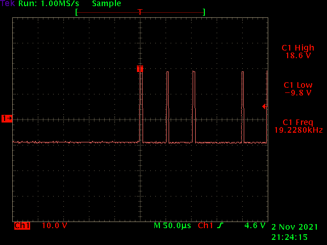
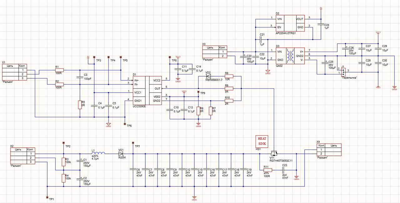
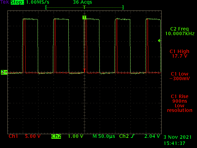
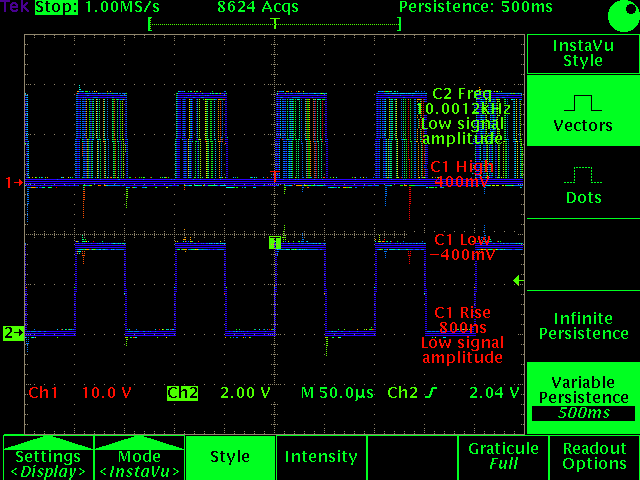
Hello! I made a custom evaluation board to make some tests of UCC53xx drivers for my applications. Below you can see the first variant of the board with UCC5320C (Ron = 10Ω, Roff = 5Ω, VCC2 = 16V, VCC1 = 3.3V). In the first test, load capacitance was equal 1nF, I feed a square wave on IN+ (IN- connected to GND1) with duty cycle 50% and I got a nice result, low rise and fall time, high duty stability on a wide range of frequencies, etc. But when I increased load capacitance to 4.7nF I obtained just noise on the driver output (see oscillogram below), very unstable duty cycle, and frequency, and even when the load capacitor was disconnected noises have not disappeared, it looks like I burned the driver. The result was the same for UCC5390E (with another scheme configuration for this driver). Do you have any suggestions on what could have gone wrong?


  • Hi, Valentyn,

    Sorry you are having difficulty with your project. I will help you resolve this issue. 

    For the oscilloscope shot, can you retake it showing input and output signals? I’d like to see what the input is versus the output. 

    Best regards,

    Don

  • Hi, Don

    Thank you for your reply! Here you can see input signal (green) with frequency 10kHz and amplitude 3.3V and output (red) which are now fully unstable, the second screenshot, made with DPO on, shows this.

  • Hi, Valentyn,

    This plot confirms my initial suspicion. 

    I believe the issue you are suffering from is not providing a solid power supply to the chip. This could be a combo of some restriction in your power delivery system for VCC2/VEE2, or the decoupling capacitors on your board. They are too far from our IC for optimal performance. They should be placed within two mm of the IC pins - please see our EVM design for an example of an optimal layout.

    This is further discussed in section 13 of the datasheet. 

    If you probe pins VCC2 to VEE2, you might catch the voltage drooping which I believe is the root cause of the issue you're seeing.

    Best regards,

    Don

  • Hi, Don,

    You were right, the problem was with the power supply. But it was so primitive that I am ashamed. Visually, I soldered IC well, but there was a high resistance between IC pin and PCB track... I will also take into account your suggestion about decreasing the distance between capacitors and IC pins in further revision of the board. But now I have very good results with UCC5390, rise and fall time is even shorter than I expected.

    Thank you for your help!

    Best regards,