This thread has been locked.

If you have a related question, please click the "Ask a related question" button in the top right corner. The newly created question will be automatically linked to this question.

TLVH431A: About abnormal fever of TLVH431A

Part Number: TLVH431A
Other Parts Discussed in Thread: TLVH431

Hi team!

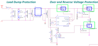
At IC2(TLVH431A),300mA flows through the REF terminal to Anode terminal, causing abnormal heat generation up to 150 degrees.
I made 5 prototypes, but they all have the same phenomenon.

Do you have any checkpoints?
There is no doubt about the constants of R1 (30.1Ω), R2 (2KΩ), and R3 (20KΩ) in the figure below.

  • Hi,

    How are you calculating 300mA though the TLVH431?

    We do not recommend to have more than 70mA as per the recommended operating conditions if the Tj < 150C.

    What is the max/min voltage across R3?

  • Hi Marcoo

    >How are you calculating 300mA though the TLVH431?

    Reading at the ammeter of the main constant voltage power supply.
    When I take off  R1, it becomes 0mA.

    >What is the max/min voltage across R3?

    Max.20V, and Min.5V.

    The standard voltage is 12V.

  • Hi Kensuke,

    It seems the TLVH431 is in comparator mode.

    The threshold with the resistor divider is 1.25V.

    The issue is that the TLVH431 REF pin can only handle 3mA ABS max but I recommend to stick below 100uA.

    During the high condition where the voltage at the top rail is 20V, the IREF pin violates this current.

    I would highly recommend to increase the series resistance to a minimum of R(min) = ((20V - 1.24V) / 100uA) - 1.24V / R2)

    Can you do this in the schematic and then try again and see if the result changes?

    I still do not understand where 300mA is going unless the device is damaged an thus you are seeing abnormal current due to that. 

  • Thank you for your advice.

    I accidentally changed the reference resistor from 30.1KΩ to 30.1Ω.
    I'm convinced.