I am planning to use the TPSM13604. I have an EVM that works as advertised above 2.5A at 6V output from a 12V rail. I assembled a prototype and I see 200mV output ripple. the only differences are the input has 1 100uf ceramic, 1 47Uf ceramic and 1 10uf ceramic. the output has 1 100uf ceramic and 1 47uf ceramic. I also used a small 100pf ss cap. else the designs are identical. I built my prototype over a large ground plane on the top layer. I am using an electronic load to evaluate the performance over various loads.
1) are the electrolytic capacitors required?
2) what other factors are effecting this large ripple voltage.
3) the input is from a bench supply, in the EVM design looks quiet but in my prototype there is <700mv noise on this line. What steps can I take to mitigate this. both designs are driven from the same supply 1 at a time.
ADDITIONAL INFORMATION
I added an additional 100uF aluminum electrolytic capacitor to the input and an additional 10uf to the output. This made no change to the noise waveforms.
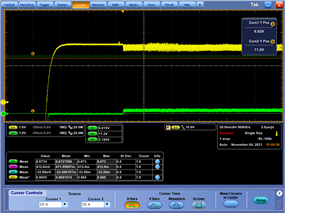
At start up, the output (SCOPE CHANEL 4) looks relatively clean for 40 to 50ms then the noise starts and continues for ever.
The same noise is visible on the input (SCOPE CHANEL 1).
Here is a closer look at the transition from low to high noise.
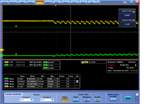
This noise is about 44KHz, which is well below the switching frequency of 300KHz. The load is a B&K electronic load set to 3 amps. I have tried lower current draw down to 1 amp and higher up to 4 amps with no significant change in the noise waveform.


