This thread has been locked.

If you have a related question, please click the "Ask a related question" button in the top right corner. The newly created question will be automatically linked to this question.

UCC256404: Deviation between WEBENCH and Calculation excell

Part Number: UCC256404
Other Parts Discussed in Thread: UCC256302, TLVH431, TLV431

Hello;

I want to make a 180w dual output design with (+30v 3A & -30v 3A) output with UCC256404 only. I do not want to use any secondary rectifier or PFC in front.

I want to get 50mV p2p output ripple. Target efficiency 90+ is fine. Switching frequency is 150Khz.

Input DC voltage will be between 280-345. Nominal will be 325VDC( 230VAC).

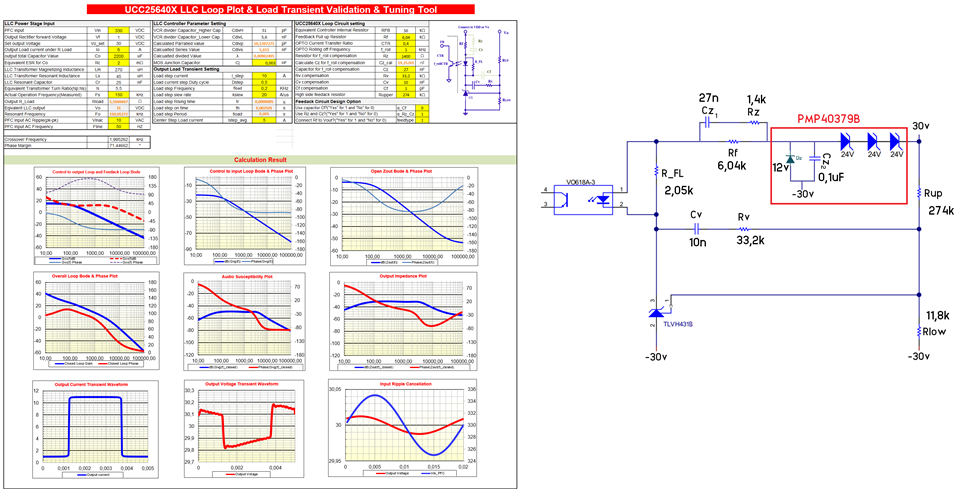
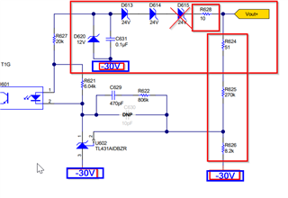
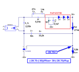
Both calculation excel and WEBENCH do not support dual output and negative voltage output. So i choose 30VDC 6A output instead. I guess results will be the same except there 2 secondary winding and feedback network is different so i am planning to copy it from PMP40379B.

Questions;

1) Do you have any suggestion for dual rail output calculation with calculation excel or WEBENCH?

2) Even i enter same parameters in both suggested part values are so different between each tool. Which tool do you suggest me to use?

3) I am glad if you show us how do fill UCC256302 calculation excell to get values in the PMP40379B  reference design. I tried but excell gives me different values than reference design.

4) i read Hybrid Hysteretic Control it has very good improvement for T. Response. I also want to implement in my design but pdf guide and datasheet  7.3.1 explain it very theoretically every real world example and suggested calculation tools (excel & webench) is based on Direct Frequency Control. So i s there any reference design using this new method. Or and working example to guide us to build our own.

Thanks in advance....

  • Hi,

    Thanks for reaching out to us.

    1) Do you have any suggestion for dual rail output calculation with calculation excel or WEBENCH?

    I would recommend using Excel based design sheet: https://www.ti.com/lit/zip/sluc675

    For having the dual output,  Please use the secondary side rectifier as given in PMP40379 reference design | TI.com. This is similar to connecting two full wave rectifiers connected in parallel.

    In the design excel sheet, output voltage and output current inputs should be entered as +30V, 6Amps.

    You can also refer the below link in which excel design calculator has been used for dual output requirement: 

    (+) UCC256403: check the PFC+LLC schematics - Power management forum - Power management - TI E2E support forums

    i read Hybrid Hysteretic Control it has very good improvement for T. Response. I also want to implement in my design but pdf guide and datasheet  7.3.1 explain it very theoretically every real world example and suggested calculation tools (excel & webench) is based on Direct Frequency Control. So i s there any reference design using this new method. Or and working example to guide us to build our own.

    All the family of these devices (UCC25640x) uses Hybrid hysteretic control which is a combinations of direct frequency control plus charge control. The excel design sheet is based on the hybrid hysteric control. 

    I hope these comments clarifies all your questions. 

    Regards

    Manikanta P 

  • Thanks for reply,

    I completed the excel calculation (My configration) except the loop circuit / feedback network.

    I will use VO618A otocoupler and TLVH431BI as shunt regulator same as sample/evo/ref boards. To make proper calculation the calculationexcel ask for the information here below;

    1)

    OPTO Current Transfer Ratio CTR ?  
    OPTO Rolling off Frequency  f_roll ? kHz

    These are not defined in the datasheet. So i am not able to calculate proper F. network.

    2) Even i know them R_FL is not able to calculate in excel

    3) for TLVH431 series referance voltage typ. 1.24v but almost all evo board reference value calculated as 1,23734 so is there any spesific reason of it?

    Thanks in advance...

  • Hi Erkan,

    Please find the responses for your questions below:

    1. The FB current source is 0uA to 82uA for UCC256404. Because only a small current is needed to set the FB signal, the CTR is towards the left on the graph where the CTR is smaller.

    Same reason for cut off frequency.

    So, You can consider CTR of 0.4 and Roll off frequency of 1kHz.

    2. Since R_FL helps to bias the TLV431, you can connect a 2kohm resistance across Photo diode.

    3. While calculating Rup and RLow , Consider the typical value of Vref in U1 datasheet (see picture below). In your case it should be 1.24.

    Regards

    Manikanta P

  • Thanks Manikanta;

    I calculated values according to your lead, Please see the results here below;

    1) Do you see any poor performance on the charts. Or all seems ok?

    2) The circuit in the red rectangle copied from PMP40379B. I do not know the purpose of it. Am i have to keep it as it is? Or it is just overkill for 180w output?

  • Hi,

    I couldn't access the file. Could you insert the file directly rather than inserting a link.

    Regards

    Manikanta P

  • Sorry i did not aware of able to upload file directly. Please see calculation excel and aplication schematic picture here below;

    0714.calculation.xlsx

  • Hi,

    Your excel calculator seems fine to me.

    However the feedback circuit needs to have modifications as given below.

    1. You need to remove one of the 24V Zener diode. These diodes are making sure voltage across Cz is 12V.

    You can find the additional details about the 12V bias in given link feedback design using TL431 by Christophe Bosso  (page number 36)

    2. There has to be a series resistance in series with these zener diodes to make sure current through them is limited.

    3. Rup and Rlow values needs to be changed such that their ratio should be (Rup/Rlow) = 47

    Regards

    Manikanta P

  • Thanks i will do that.

    How did you calculate 47 ratio for voltage divider resistors?

    Instead of using single transformer and calculate leakage is hard for me so i will use seperated ferrite inductor for resonant tank. Could you advice me a core material.

  • Hi,

    You just need to equate the currents that are going through Rupper and Rlower to find out their ratios.

    Magnetics design involves optimization. So, it's not a straight forward. So, I would recommend you to go through the following reference: Fundamentals of Power Electronics | SpringerLink.

    Could you also send me an email (m-pallantla@ti.com ) so that I will share you the other links to get you started on LLC magnetics design.

    Regards

    Manikanta P