This thread has been locked.

If you have a related question, please click the "Ask a related question" button in the top right corner. The newly created question will be automatically linked to this question.

UCC28180EVM-573: PF issue when connected the UCC28180EVM-573 and the UCC25630-1EVM-291

Part Number: UCC28180EVM-573
Other Parts Discussed in Thread: UCC28180, UCC256301, UCC25630-1EVM-291, , PFCLLCSREVM034

Hello,


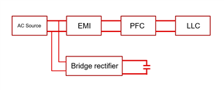
I’m designing power supply system using UCC28180 and UCC256301.

I evaluated these products using “UCC28180EVM-573” and “UCC25630-1EVM-291”, but power factor was not corrected. Tested conditions and result are below,

<AC Input>

Supplied 115 V(60 Hz) to “UCC28180EVM-573(J1) and UCC25630-1EVM-291(J1).”

<Connection>

Connected between “UCC28180EVM-573(J3) and UCC25630-1EVM-291(J2,J3)”, and “UCC28180EVM-573(J2) and UCC256301 RVCC out(Pin 12).”

<DC Output>

Connected UCC25630-1EVM-291(J5) to electronic load(constant current).

<Result>

Power factor was about 0.86 maximum.


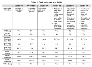
From the UCC256301 datasheet and other topics of E2E, I found RVCC voltage of UCC256301 is not enough to supply VCC of UCC28180.


So I switched DC input of UCC28180(J2) from RVCC of UCC256301 to 15V DC power supply, but I cannot correct the power factor yet.


Furthermore, an overall power factor fell to 0.6 when I changed the AC input of “UCC28180EVM-573” and “UCC25630-1EVM-291” to 400 Hz.


Will there be the method to improves these power factors? I have no idea to solve this problem.


Best regards.

  • Hello Tomohiro-san,

    There's a lot to unwrap here. 

    The first thing to do is verify that the UCC28180EVM is working properly. Simply remove the UCC25630EVM and measure your power factor with 0.2A, 0.5A and 0.8A loads and confirm that they are similar to figure 4 in the UCC28180EVM User Guide: https://www.ti.com/lit/pdf/sluuat3 . 

    Let me know your results so I can try to help you isolate your issue.

    Regards,

    Ray

  •  Hello Ray,


    I test the UCC28180EVM-573. Tested results are below,


    Output-current    Power-factor

    0.2A                     0.994

    0.5A                     0.998

    0.8A                     0.998


    The result looks like it has no problem.

    Also, I test the UCC25630-1EVM-291 but the result has no problem too.

    When I connect the UCC28180EVM-573 and the UCC25630-1EVM291, the power factor decreases.

    Are these two ICs or evaluation boards incompatible?

    Best regards.

  • Hi,

    I would recommend using our latest generation LLC controller (UCC25640x) EVM. 

    Here is the comparison table for LLC controllers:

    Please find the links below to our latest gen LLC controller datasheet and it's EVM:

    UCC256404 data sheet, product information and support | TI.com

    https://www.ti.com/tool/UCC25640EVM-020

    Regards

    Manikanta P

  • Hello Tomohiro-san,

    I don't see why the two EVMs would be incompatible (other than the RVCC issue you noted with the UCC256301).

    Now that you've confirmed that each EVM is functioning on their own:

    1) Connect the EVMs output of UCC28180EVM-573 (using the 15V external supply on VCC) to the input of UCC25630-1EVM291

    2) Put 10A load on the output of UCC25630-1EVM291 (TP11, TP23)

    3) Measure the voltage at the input of UCC25630-1EVM291 (TP5, TP2)

    4) Measure the voltage on the output of UCC25630-1EVM291 (TP11, TP23)

    5) Use on Oscilloscope to look at the output of UCC25630-1EVM291 (TP11, TP23) to ensure it is steady DC

    6) Record your PF

    I think somewhere along these steps you will discover the issue.

    Regards,

    Ray

  • Hello Ray-san,


    I tested the converters under conditions you suggested. Tested results are below,


                               PFC-Input           PFC-Output        LLC-Output        Power factor

    12V/10A             114.8VAC            388VDC              12.0VDC             0.787


                                Min        Average    Max

    PFC-Output       374V       388V         404V

    LLC-Output        9.8V       12.0V        14.2V


    I observed the voltage with oscilloscope.

    PFC-Output and LLC-Output have switching-noise, but the Average-voltages were stable.

    Any other points I should check?

    Best regards,

    Tomohiro

  • Hello Tomohiro-san,

    That variance on the outputs is much larger than expected, especially on LLC output.  That doesn't appear to be switching noise but some instability.  How does the LLC output compare to figure 10 in the LLC user guide? https://www.ti.com/lit/ug/sluubq8b/sluubq8b.pdf

    What are you using for a load, is it an eload a resistive load or something else?  If it's an eload, do you have the voltage sense connected to the output?  Consider the lead length and wire gauge to keep the impedance and inductance low.  Also evaluate how you're connecting the two EVMs together; again, short wire with sufficient gauge.

    When you tested the LLC EVM on it's own and reported that it worked as expected, did you have the 10A load applied?

    Make sure your VCC supply isolated and probe it while the output is loaded to make sure that supply is behaving properly and not dropping out.

    Regards,

    Ray

  • Hello Ray-san,


    I’m sorry.

    I answered the minimum voltage, the average voltage and the maximum voltage about the output voltage last time.

    But the minimum voltage and the maximum voltage were the spike voltage. (Not ripple voltage)


    I judged the UCC25630-1EVM-291 do not have problem from the following results.


    Tested results and conditions are below,

    <Evaluation module>

    UCC25630-1EVM-291


    <Condition>

    Supplied 115V(60Hz) and 390V(DC).

    Connected UCC25630-1EVM-291(J5) to electronic load(constant current).


    <Results>

    12V/10A                    Min                              Average                     Max

    Output voltage          11.6V(spike)                11.8V                         12.1V(spike)


    I observed the voltage with oscilloscope. (Probing the TP11 and the TP23)

    When I connected the two evaluation modules, I observed the voltage spike by the PFC switching noise.

    Best regards,

    Tomohiro

  • Hello Tomohiro-san,

    You showed that each EVM works as expected when tested individually but that the PF drops when you connect them together.  I can't see any reason that the two EVMs are somehow incompatible. Of course there is always the possibility that there is some unexpected interaction.

    I've given you things to look at and consider, but ultimately you need to debug the issue.  I can't discern very much from just voltage readings so if you'd like me to be able to help, you'll need to provide waveforms for all conditions we've covered above.  Also a picture of your complete setup, the setting on your eload and anything else you think may be relevant. 

    Regards,

    Ray

  • Hello Ray-san,


    I prepared two AC power-supply units and reevaluated the connected circuit. Tested results are below,

    <Condition>

    UCC28180EVM-573 : AC power-supply(60 or 400Hz, 115V), DC power-supply(DC15V)

    UCC25630-1EVM-291 : AC power-supply(60Hz, 200V), DC power from the UCC28180EVM-573(DC390V)

    Connected UCC25630-1EVM-291(J5) to electronic load(constant current).


    <Results>

    LLC Output Current          Power Factor

                                              60Hz                   400Hz

    1A                                      0.935                   0.543

    2A                                      0.972                   0.733

    5A                                      0.992                   0.930

    8A                                      0.996                   0.958


    I thought that the UCC25630-1EVM-291 has the cause of the power factor aggravation from the upper result.


    When I connected the UCC25630-1EVM and the UCC28180EVM and I used the same AC power supply unit with the UCC28180EVM and the UCC25630-1EVM, I observed below the wave pattern of the AC electric current.

     60Hz-5A-全体図.TIF

    (Biue: PFC output voltage, Green: Input current of the AC power-supply)

    (Input frequency: 60Hz, LLC-output: 12V/3A)


    I understood that the AC input current has abnormal in every half cycle.

    So, I doubted a half-wave rectification circuit.


    When I checked the evaluation module schematics, I felt the AC filter of the UCC25630-1EVM-291 is useless on this evaluation condition.


    First, I took off the X-capacitors(C3, C4, C6). Tested results are below,

    <Condition>

    UCC28180EVM-573 : AC power-supply(60 or 400Hz, 115V), DC power-supply(DC15V)

    UCC25630-1EVM-291 : AC power from the AC-input of the UCC28180EVM, DC power from the DC-output of the UCC28180EVM. Connected UCC25630-1EVM-291(J5) to electronic load(constant current).


    <Results>

    LLC Output Current          Power Factor

                                              60Hz                   400Hz

    1A                                      0.955                   0.562

    2A                                      0.931                   0.733

    3A                                      0.872                   0.785

    4A                                      0.899                   0.825

    5A                                      0.860                   0.783


    From the upper result, it turned out that only the X-capacitors do not have the cause of the power factor aggravation.


    Next, I took off the Bridge-Diode(D3). Tested results are below,


    <Condition>

    UCC28180EVM-573 : AC power-supply(60~400Hz, 115V), DC power-supply(DC15V)

    UCC25630-1EVM-291 : AC power from the AC-input of the UCC28180EVM, DC power from the DC-output of the UCC28180EVM. Connected UCC25630-1EVM-291(J5) to electronic load(constant current).


    <Results>

    LLC Output Current          Power Factor

                                              60Hz                   400Hz

    1A                                      0.923                   0.402

    2A                                      0.970                   0.607

    5A                                      0.991                   0.868

    8A                                      0.998                   0.915


    From the upper result, it turned out that the LLC filter has the cause of the power factor aggravation.

    But, I can not understand why the Bridge-Diode deteriorated the power factor.

    Would you explain it if you understand the cause of this phenomenon?


    Also, the power factor in case of 400Hz is not so good, but is there the method to improve this?


    Best regards,

    Tomohiro

  • Thank you for the additional information Tohohiro-san.  Since you have isolated the issue to the UCC25630 EVM, I am forwarding this E2E to my colleague who is the expert on our LLC products.

  • Hi Tomohiro,

    when you connect both the EVMs together, the connection for HV pin should be as below.

    When you connect the diode bridge which is in the UCC256301 EVM to a separate AC source, it will deteriorate the power factor as the harmonic content is very high.

    The PFC EVM and it's EMI filter is designed assuming input frequency 50-60Hz. when the input line frequency changed to 400Hz, I would expect a change in the design. So, pf need not be maintained at such a higher input line frequency.

    Regards

    Manikanta P

  • Hello Ray-san and Manikanta-san,


    Thank you for teaching the connection method.

    But I have two questions.


    1. You taught me AC-line(HV) of the UCC25630-1EVM connected the back of the EMC-circuit. But your company’s product is supplied by the front of the EMC-circuit. (For example, the PFCLLCSREVM034.) Why should the AC-line(HV) of the UCC25630-1EVM be connected by the back of the EMC-circuit? Also, if I design power supply system using UCC28180 and UCC256301, which connection method do you think is recommended?


    1. AC-line of the UCC25630-1EVM is used X-capacitor, bridge-diode and resistance. I felt that these are not necessary. What would these be connected for?


    Best regards,

    Tomohiro

  • Hi Tomohiro,

    Please find the answers below:

    1.  UCC256301 has an x-cap discharge feature. Because it's an standalone EVM (no PFC circuit in this EVM), to demonstrate the x-cap discharge feature, additional bridge rectifier and x-capacitor is used in that particular EVM. Also, If the HV pin don't see any AC zero crossing at HV pin in this EVM, controller goes to fault mode. So, for the controller to work in this standalone EVM, this additional circuit is necessary.

    Incase you are using PFC in front  (For example, the PFCLLCSREVM034) , the HV pin connection should be connected to x-cap which is the part of the EMI filter (which is similar to below). 

    so, for your design follow the connection given in PFCLLCSREVM034 EVM.

    2. When you make connection as below, since bridge rectifier connected in parallel, it's power factor will be poor. 

    So, when you use a PFC along with the standalone EVM, you do not need to have this bridge rectifier. 

    In conclusion, follow the schematic given in PFCLLCSREVM034 when you design your own board. 

    Regards

    Manikanta P