Hi team,
My customer use TPS65132 in their project, now they meet below issue, could you help give some suggestions? Thank you!
Customers are experiencing an issue with the open gesture standby current increase exceed when using the TPS65132.
TPS65132 increase: 2.2 mA
OCP2131B increase: 1.7 mA
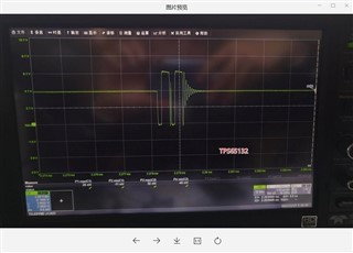
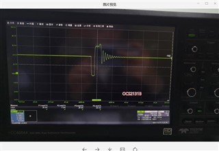
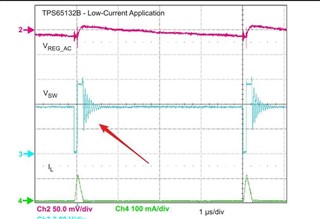
Both ICs operate PFM mode after gesture standby is turned on, the difference between the SW waveform is as follows: The TPS65132 will charge twice, and the OCS2131B will only have one charge. The datasheet of TPS65132 also shows a single charge.

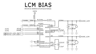
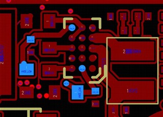
Below are the schematic and PCB.
Regards,
Ivy