This thread has been locked.

If you have a related question, please click the "Ask a related question" button in the top right corner. The newly created question will be automatically linked to this question.

LM25085: Input Capacitance

Part Number: LM25085

Hello,

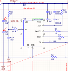
We have a device that needs to be re-designed. It uses an LM25085 buck converter. The voltage to the converter is sourced from a nearby lithium ion battery pack. The spec states that the input capacitors(C9 and C13) are necessary to limit the input voltage ripple and supply current during the "on-time" of the switch.

We've found that we may need to remove these input capacitors to the device (C9 and C13) .Could the converter work without the input capacitors/ how would this affect the efficiency?

Another option we are working with is adding a resistor in series with C9 and C13. Increasing the resistance of this resistor would decrease the efficiency of the converter, but is there a point where increasing the resistor's value would render the IC inoperable?

Any thoughts or input on the two possible circuit modifications would be appreciated. Thanks!

  • Hi Matthew,

    Input capacitors are required close to the FETs for a synchronous buck regulator (or in this case FET and diode for a non-sync design). This capacitance must be as low impedance as possible as high-frequency current flows in the "hot" loop of the input cap, FET and diode. See app note SNVA803 for optimal cap placement in a power stage layout. There should be no reason to add series resistance here.

    If the concern is related to inrush current when the capacitors are first connected to the battery, you can use a series inductor to provide some impedance or a load switch to gradually increase the voltage.

    Regards,

    Tim