


Hi,
I'm trying to copy TPS23730EVM-093 design with using a POE RJ45 Connector with integrated magnetics instead (Say ARJ11A (abracon.com)).
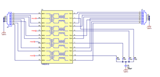
Reference Design:
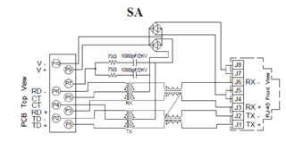
POE Connector:
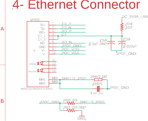
I'm seeking guidance on how to connect the GND and Shield pins of this connector,
- should I treat them as the Earth in the reference design schematic?
- Should connect to the SHIELD? (MH1 and MH2)?
- Should C29 and C59 be referenced to Pin 7 as it is done or that is wrong?
- Which plane should the TX/RX diff pair be referenced to? how can I connect them to an on-board ethernet controller that is biased by a 3V3 and GND?
