This thread has been locked.

If you have a related question, please click the "Ask a related question" button in the top right corner. The newly created question will be automatically linked to this question.

BQ2972: Dead battery charging not happening

Part Number: BQ2972

Hi TI team,

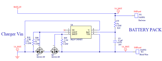
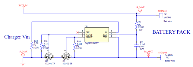
Im using BQ29729 part for my battery protection. The problem im facing is once the battery is fully drained, this protection circuit not allowing battery to charge again. Until i make short between V- to Vss system not coming back to normal charging/Working mode.

The battery spec is 3.7V 200mA Li-ion battery and it has 3V UV protection. My Circuit has series RDSon (COUT+DOUT) is about 100mOhms. It is more or less allowing 1A for charging current though my battery not charging properly.

Need help to resolve the issue . 

Attaching circuit for your reference. 


  • Hello Bala,

    I am a bit confused on the 3-V UV protection, the BQ29729 has an UV of just 2.3-V. At most this part can do UV protection of 2.8-V.

    100-mOhm seems rather high for RDSON. At 1-A this would equal to a 100-mV voltage drop across the FETs which is equal to the OCC threshold for the BQ29729. 

    I believe you may be triggering OCC protection during charging. Shorting V- and VSS would make it go back to normal. What is the voltage of V- to respect to Vss when this occurs?

    Best Regards,

    Luis Hernandez Salomon

  • Hi Luis,

    3V UVP is from battery PCM side. I know this particular IC is meant for 2.3V UV. ( Note:  My charging current is only 200mA for this battery) 

    if 100mOhms is huge value what should be the correct RDSon i should choose. 

    The voltage across this V- and VSS is around  -3.7V during this scenario.

    Would it solve the issue if i use FET with less RDSon? Please advise.

    Thanks,

    Bala

  • Hello Bala,

    I thought you mentioned 1-A during charging, at 200-mA it should not have issues charging unless there are other protections triggering. UV should not be triggering so that should not be affecting it.

    What are the voltages at the pins of DOUT and COUT? Can you post a schematic or block diagram of your system?

    Best Regards,

    Luis Hernandez Salomon

  • Hi Luis,

    During this scenario Cout measured as 0V and Dout measured as 3.4V. 

    Could you please share you mail id so that i can send you the snap of this circuit.  

  • Hi Luis,

    One more doubt, My battery has its own PCM module. Do we really need to have one more protection circuit in my board?

    PCM circuit in battery:

    PCM circuit in my board: 

    In BQ2972x datasheet everywhere it is mentioned like connect the Cell+ and Cell-. Does it means we need to connect only the battery cell ? What if it has its own protection PCM ? how this will work here in this case? Kindly advise. 

  • Hello Bala,

    The need for more protection circuits would depend on the standards that you want to fulfill for your application. Most BMS have some sort of secondary battery protections, but this would depend on your need and application.

    Yes, only one battery cell, you'd want to connect the BQ2972xy directly to the cell. It seems your battery includes it's own MOSFET protection system. What protection does the PCM includes? I'd be worried about having 4 FETs in series, this would also waste more energy. Although I am not sure how your PCM would affect the BQ7972xy. I believe it should still work.

    If COUT is low, then it is likely that this was the over-current protection triggering, as you mentioned the battery would be discharged, so it is unlikely to be OV protection. You mentioned a 1-A charging current, this would likely trigger the protection, based on your FET resistances. What's the V- to Vss voltage when the charger is removed? The device should recover once the voltage in V- is higher than the OCC voltage threshold.

    Best Regards,

    Luis Hernandez Salomon

  • Hi Luis,

    Im still not able to conclude where this issue could be. The scenario is like this. 

    I have connected the charger first of all and no battery connected at this moment i observe 0V at BAT to VSS pin. I think it suppose to provide charger voltage as it is. Please advise if this issue is something usual. 

    If my component selection is wrong what should be the FET RDSon value? my current RDSon value is 54mOhms Please advise. 

    Thanks, 

    Bala.

  • Hello Bala,

    You should be connecting the battery first, then the charger. What is the charger voltage? Did you read the conditions detailed in 9.4.1 Normal Operation of the datasheet?

    FET RDSon depends on the charge currents, discharge currents, short circuit current, etc. It depends. Adjust based on worst-case scenarios and follow the Design Procedure example of Section 10.2.1 and 10.2.2.

    What protection features does the PCM have?

    Best Regards,

    Luis Hernandez Salomon