This thread has been locked.

If you have a related question, please click the "Ask a related question" button in the top right corner. The newly created question will be automatically linked to this question.

BQ24170: Switiching Node Voltage with dips

Part Number: BQ24170

Hello E2E Team,

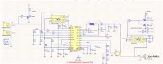
we have a problem with the design of our battery charger. We designed it like it is described in figure 23 (chapter 10.3) of the datasheet.

Input Source: 12V
2 Cells

Now we are facing the problem, that the switching node voltage (Pin 1, 24) has a voltage dip every 500 ms:

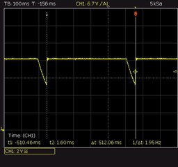
Can you explain this behaviour? Do you have any suggestion here?

Many thanks and best regards,

Thomas

  • Dear Thomas,

    Does this happen only when the battery is removed? Does this waveform appear on SRN as well? This is more than likely the battery absent detection.

    Thanks,

    Mike Emanuel

    Please click "Resolved" if this answered your question.

  • Yes, it only appears when no battery is connected. So the system cannot be used if there is no battery connected? The charger IC cannot supply the system in the configuration of figure 23?

    Another problem is, that the battery is not charging. If I connect the battery the current consumption is only 7 mA and the battery is not charged.

    Do you have a suggestion here as well?

    Thanks,

    Thomas

  • Dear Thomas,

    Figure 23 assumes that the battery is unremovable. This is why you can tie the SYSTEM directly to the output of the inductor. In this case, the system will track the battery voltage. With no battery present, the output will go through battery absent detection.

    If however, you would like to have system power from the input while the battery is not attached, you need to incorporate the BATFET as shown in Figure 19.

    Can you please describe in detail more about your setup? What is the battery voltage you are applying, what is the programmed CELL pin voltage?

    Thanks,

    Mike Emanuel

    Please click "Resolved" if this answered your question.

  • Hi Emanuel,

    Okay that sounds reasonable. Thank you!

    Our setup would be a USB-C PD Input between 9V and 15V. Right now, we are supplying the Charger IC with 12V. Battery voltage would be 8.4V, so the Cell pin is floating.

    Many thanks and best regards,

    Thomas

  • Dear Thomas,

    We will get back to you next week after the Thanksgiving holiday.

    Thanks,

    Mike Emanuel

  • Dear Thomas,

    Please make sure you have enough headroom between the input to the battery charger and the maximum battery charge voltage. As this is a buck charger, the input to the converter must always be higher than the output battery voltage.

    Thanks,

    Mike Emanuel

    Please click "Resolved" if this answered your question.

  • Hi Mike, 
    I have a supply voltage of 12V her on my test case. So there shouldn't be a problem with the headroom, I assume?

    Attached you can find our schematic. Can you see an error here?

    Many thanks and best regards

    Thomas

  • Dear Thomas,

    My schematic review is as follows:

    1. Confirming 4 A charge current. For this application we typically recommend a 2.2 uH inductor and 30 uF of output capacitance. See Table 3 in Section 9.3.22 for more details.

    2. Confirming 2 A input current limit.

    3. Confirming ACOV of 14.72 V and ACUV of 4.60 V.

    4. Confirming disabled termination and safety timer.

    5. Confirming 8.4 V battery voltage regulation.

    6. We recommend a 0.1 uF capacitor from SRP to AGND.

    7.  We recommend a 0.1 uF capacitor from ACP to AGND.

    With an input voltage of 12 V you will have enough headroom for an 8.4 V battery.

    Thanks,

    Mike Emanuel

    Please click "Resolved" if this answered your question.

  • Hi Mike,

    thanks for the answer.

    Do you have any explanation, that the battery is not charging? I cannot find any problem here.

    Many thanks and best regards,

    Thomas

  • Dear Thomas,

    Can you please clarify if you are seeing that the 500 ms triangular waveform appears on the SW voltage? I would expect that to be the SRN voltage with no battery applied.

    What is the battery voltage you are connecting to the charger when it cannot charge? Can you send a waveform of the input voltage, SW voltage, battery voltage, and charge current when this is happening?

    Thanks,

    Mike Emanuel

  • Hi Mike,

    No, I don't see the 500ms triangular waveform. The battery is connected and the device is working. But unfortunately it is not charging. 

    The waves are all continous voltages with no dips, when battery is connected. But the charger doesn't work when I supply 12V input voltage. The current consumption is about 5 mA. 
    Battery voltage = 7.679 V 
    SW voltage = 7.679 V
    Input voltage = 11.998 V
    charging current = 5.4 mA

    Many thanks and best regards,

    Thomas

  • Dear Thomas,

    What is your TS voltage when this is happening? Do you have the proper thermistor attached? Without a thermistor, your TS voltage is 95.1% of VREF or 3.137 V. Any voltage on TS above typical 73.5% of VREF suspends charge.

    Thanks,

    Mike Emanuel

    Please click "Resolved" if this answered your question.

  • I am using the 103AT like described in the ref design.
    The TS Voltage is 1.689 V. So that should be okay, right?

    Thanks,

    Thomas

  • Dear Thomas,

    A TS voltage of 1.689 V is 51.18% of the 3.3 V VREF, so this should be okay.

    Do you have the STAT pin pulled up to VREF through a resistor, or could you do this if you do not? I would be curious to see the voltage of the STAT pin during this operation. Please capture it on an oscilloscope if you are able to observe it.

    Thanks,

    Mike Emanuel

  • Hi Mike, 

    sorry for the late reply. 
    I tried to pull up the STAT pin and now it is charging. Many thanks for this hint! 

    But I still have one problem. The charge current is now at about 300mA@12V. Can you explain this with the schematic above? Normally, it should charge with 2A.

    Many thanks and best regards,

    Thomas

  • Dear Thomas,

    Glad that worked!

    What is the battery voltage when this is happening? I take it the input voltage is 12 V based on previous discussion.

    Thanks,

    Mike Emanuel

  • Hi Mike,

    The battery voltage is around 7.1 V.

    Thanks,

    Thomas

  • Dear Thomas,

    What is your ISET voltage currently?

    What happens if you set the R60 resistor to 13.8 kOhm? Currently you have the ISET pin programmed to 0.819 V (for 4.094 A charge current) above the valid ISET input range which goes up 0.8 V.

    Thanks,

    Mike Emanuel

    Please click "Resolved" if this answered your question.