This thread has been locked.

If you have a related question, please click the "Ask a related question" button in the top right corner. The newly created question will be automatically linked to this question.

BQ2973: protective circuitry BQ29737/BQ29707/CSD16327Q3T

Part Number: BQ2973
Other Parts Discussed in Thread: CSD16406Q3

Hello,

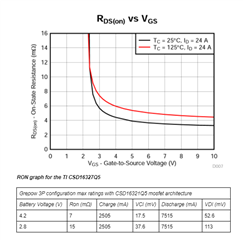
I would like to run my protective circuitry design by you.  I am using a 3P Grepow 704230 (835mAh) configuration that can charge at a maximum of 2505mA (1C) and discharge at a max rate of 7515(3C).  The system needs to shut off under 2.8V and over 4.28V maximum.  The two chips that came to mind are the BQ29707 and the BQ29737 because they are both either currently available or in the will be in the near future.   Initially, I copied the basic design that was in the data sheet of the BQ297XX that uses the CSD16406Q3 mosfets.  However, when the battery approaches 3V the on state resistance for the mosfet gets really high.  Therefore, I was looking at the CSD16327Q3T as a replacement.  Can you please take a look at my design and table that I used to this conclusion and let me know if my thinking is correct or not?  (Ron is for two mosfets in series as in the design) Thank you.

060045-001-BMS.pdf

  • Hello Kornelis,

    For your schematic, I would recommend you follow the Section 10.2 Design Procedure shown in the datasheet. I would also recommend you see the BQ29700EVM schematic for reference. In short, you are missing the ~5.1-MOhm resistance across the gate-source of your FETs, these allow for the gate-source capacitance of your FETs to discharge.

    Yes, you are completely right, ideally you would want your FET's RDSON to be in the flat voltage region as much as possible for your operating conditions. Your FET may be okay.

    Keep in mind the OCC/OCD/SCD thresholds when selecting a part or FET. Assuming a OCC of -0.090-V (BQ29707 part) and worst-case cell voltage of 2.8-V with a RDSON of ~15-mOhm, your maximum charge current could be (0.090-V)/(15-mOhm) = 6-A before OCC is triggered, your charging is within specs so it should be okay. For the BQ29737 part, your maximum charge current, before OCC, would be ~3.33-A, still within your charging spec.

    Similarly you can do this with OCD and SCD with your part thresholds and RDSON to find when these would trigger. Calculate these and see if these work for your system.

    If these seem okay, your design should have no problems.

    Best Regards,

    Luis Hernandez Salomon

  • Hi Luis,

    Thank you for your response.  Initially, I had the 5.1M resistors in my design but had taken them out to save space, since I was under the impression they are optional according to the data sheet.  I'll put them back in if needed. 

  • Hello Kornelis,

    You should have these to ensure proper FET operation. Gate capacitance may lead to unexpected behaviors. The resistor will help deplete the gate charge and help with FET turn-off.

    Best Regards,

    Luis Hernandez Salomon

  • Thanks for the response.  I'll put them back in. appreciate the help! :-)