This thread has been locked.

If you have a related question, please click the "Ask a related question" button in the top right corner. The newly created question will be automatically linked to this question.

BQ25570: Instability of Vout and Vstor signals

Part Number: BQ25570

Hello, I was forwarded here by TI support services to get the best support for our issue.

We are using BQ25570 irradiated by a 600mW (maximum) solar panel.

When we are adjusting the light exposure so the panel will produce about 300mW (~160mA), after some time of charging operation of the batter, it seems like Vstor and Vour are getting really unstable.

*for the test demonstrated below, no peripherals were connected to Vout and Vstor. Only a battery ass connected to Vbat.

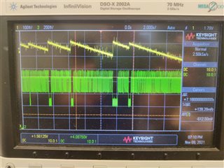
Vstor is varying in a ~700mV peek to peek, and Vout is just really not clean:

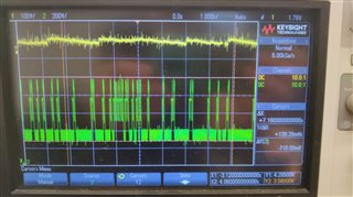
 Above: Vstor (green) is varying in a ~700mV amplitude.

Above: Vout (yellow) is not stable. Some cases were much worst but weren't documented. 

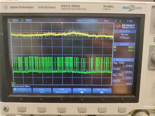
for reference, here is a much better plot of the signals in charging operation:


I can send more supporting documents if needed, privately.

We hope you might saw this situation before and can recommend a solution to us.

 Thanks,
Raz.

  • Hi Raz,

    Can you send your schematic?  Is the small bypass capacitor VSTOR to GND placed as close to the IC as possible?  Also what is the DC voltage on VSTOR and VMPP seen at VINDC?  If VSTOR drops below 2.0V, the charger enters cold start.  Did you hot plug a battery (i.e. attached a battery with a voltage > 100mV at VSTOR)?  If so then the PFET between VSTOR and VBAT is likely not closed and so the battery cannot supply power to VSTOR and therefore VOUT buck converter.

    Regards,

    Jeff 

  • Hi Jeff, thanks for your reply.

    Can I send you the schematic privately?

    And for the rest of your questions:

    *bypass cap is located as much as possible to the VSTOR terminal on the IC.
    *Didn't understand the question about VINDC, can you rewrite it, please?
    *VSTOR doesn't go below 2V.
    *I attached a battery at VBAT, not VSTOR.

    Raz.

  • Hi Raz,

    I am going on holiday tomorrow through 12/8.  So I have notified my colleague to help going forward.  Regarding my question, what is the minimum voltage (the solar panel max power point voltage) seen by the charger's VINDC pin.

    Regards,

    Jeff

  • Oh, I see.
    So, the VINDC was about 2.3Voc and stable, and a minimum of 1.7V of effective voltage (measured while the panel was connected to the chip).
    The test we made was to see how the chip is behaving with a steady level of input power. so the Voc voltage remained the same.

    Let me know to who should I send the schematic, privately.
    I can also send the report of the test we did if you think it could help.

    Happy Thanks Giving,
    Raz.

  • Dear Raz,

    You can friend me to send your schematic. Taking offline.

    Thanks,

    Mike Emanuel