This thread has been locked.

If you have a related question, please click the "Ask a related question" button in the top right corner. The newly created question will be automatically linked to this question.

TPS23881: TPS23881 Sifos testing fail of item: PWRON_unbal & mps_dc_pwrdn

Part Number: TPS23881
Other Parts Discussed in Thread: CSD19538Q3A

Hi Team,

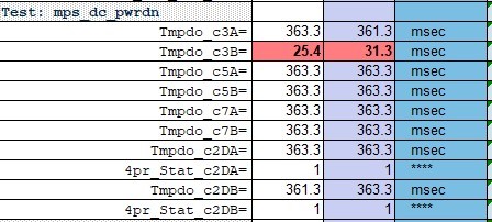
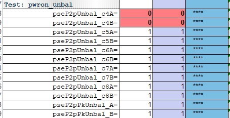
Customer is using our TPS23881 as a semi-auto mode, and found 2 fail items when running the Sifos testing that: 'PWRON_UNBAL' & 'MPS_DC_PWRDN', detail as below:

And when running the testing, customer's TPS23881 configuration is:

                   //Set all channels in semi-auto mode

                   0x12 set to 0xAA

                   //Enable all channel's DC disconnect

             0x13 set to 0x0f

             //Set  4pair ports in 4 pair 90W mode

            0x29 set to 0xFF

             //Enable all channels' detection and classification

            0x14 set to 0xFF

And before the ports power on, the SW will detect whether this port is single PD, if yse, then will set 0x2D to enable NCTnn & NLMnn, and enable 2P ILIM/PCUT for 4P power off.

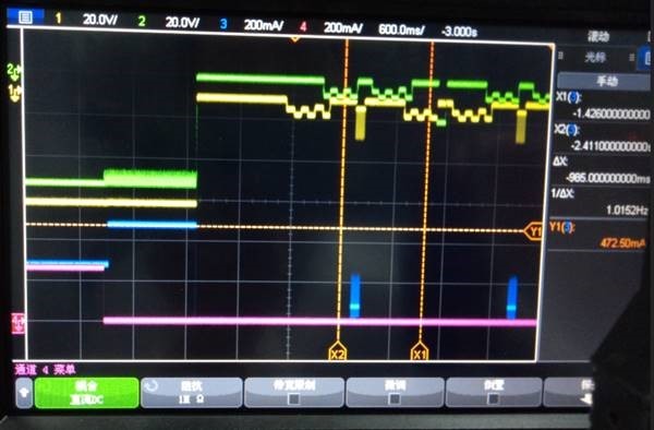
Meanwhile, per monitor the waveform when doing the 'pseP2PUNBAL_C4A ' testing, they found there is 470mA at altA & 0mA at altB, and then after ~1S, this port be power off and PSA3000 report fail.(waveform picture as below).

Base on the information above, could you kindly help to check what's the potential reason? and share us your suggestion or other items need to be further verified.

Thanks & BRs,

Cheney

  • Hi Cheney,

    Can you share the full test report in .xls with me? In the meantime, can you ask them to set the device in auto mode and run the test again? Thanks.

    Best regards,

    Penny

  • Hi Penny:

    The Result is same when we set the device in auto mode and run the test again.

    We find that  'pseP2PUNBAL_C4A ' testing is related to the MOS model. The MOS we use is CJU15N10. If we change the MOS to CSD19538Q3A which is use in TPS23881 Demo, it is ok(470mA at altA & 0mA at altB). Besides, we find that 580mA at altA & 10mA at altB is ok when use MOS CJU15N10. Therefore, the problem is when one pair set  is powered off.

    Please help to see what there is the problem with this MOS.

    Beside, we find that  'Tmpdo_c3A ' testing is related to the value of port capacitor. If we change the value of port capacitor in TPS23881 Demo from 0.1uF to 0.022uF, it is fail too.


  • Hi Xiwen,

    I can't find CJU15N10 datasheet online so I couldn't comment on the MOS. Regarding the port capacitance, in IEEE standard there's some capacitance requirement for the port PD maintain power signature. So it is recommended to follow our reference design in order to pass the sifso test. 

    Thanks,

    Penny

  • Hi Cheney,

    CJU15N10 datasheet online website is https://www.sekorm.com/doc/2311652.html.

    When doing the 'pseP2PUNBAL_C4A ' testing, they found there is 470mA at altA & 0mA at altB. First 1S, this port does't power off (waveform picture as above).Why this port turned off after ~ 1s?

    What is capacitance requirement in detail for the port PD maintain power signature in IEEE standard ?

    We find that the port capacitance value only affects the falling speed of voltage when the poft power off. The result of 'Tmpdo_c3A ' testing is -1 when using 0.1uF, what does the result value '-1' mean? The result of 'Tmpdo_c3A ' testing is about 20~30ms when using 0.022uF. Please try to replicate the problem to see if it's just a matter of test equipment criteria?

  • Hi Xiwen,

    Can you send me the full test report? It should have detailed explanations about the fail mode.  

  • Hi Xiwen,

    "-1" seems to be a tester issue to me. Looks like it is not able to measure the timing. Is it possible to capture the port voltage and current waveform when you run this single test and you can measure the time from the waveform to verify if it is tester issue or your system issue. 

  • 1、

    When doing the 'pseP2PUNBAL_C4A ' testing, they found there is 470mA at altA & 0mA at altB. First 1S, this port does't power off (waveform picture as above).Why this port turned off after ~ 1s?

    Please help to see what there is the problem with the MOS  CJU15N10?

    2、

    The  waveform of 'Tmpdo_c3A ' testing is below.

    Tmpdo_c3A.rar

    3、What is capacitance requirement in detail for the port PD maintain power signature in IEEE standard ?

  • Hi Xiwen,

    I will review the log next week and get back to you. 

  • Is there a conclusion on MOS problem?look forward to your reply.

  • Hi Xiwen,

    I looked into the MOSFET datasheet and didn't find anything alarming. 

    When doing this unbalance test using the CJU15N10 MOSFET, did you see any fault reported from PSE side?

  • Overcurrent fault

  • Hi Xiwen,

    Can you please capture the port current waveform along with the port voltage waveform when this issue happens and send me the register dump after the fault happens?

  • The waveform is in the first conversation. Please provide solutions as soon as possible.

  • Hi Xiwen,

    Can you send me registers values of 0x06,0x08,0x0A? Thanks. 

  • 0x06:0x04

    0x08:0x00

    0x0A:0x00

  • We can provide 2pcs MOS CJU15N10 to reproduce the problem, so as to solve the problem as soon as possible.

  • Hi Xiwen,

    It is likely the MOSFET issue. Have you tried other vendor's MOSFETs to find the potential cause of this? If you ship the MOSFET to us, we will not be able to test on the MOSFET until early Jan due to the holiday season in US. Thanks. 

  • There is also a problem when replacing other MOS. Please provide possible reasons. 

    We found 470mA at altA & 80mA at altB is ok. What happens when the channel current is less than 75mA?

    Please provide mailing address.

  • Hi Xiwen,

    Please work with your local FAEs on the shipping.

    Just to understand the test conditions, there's no issues when using CSD19538 MOSFETs and the issue only happens with CJU15N10, right? 

  • Hi Xiwen,

    Please work with your local sales team on the logistics. Thanks. 

  • Hi Penny

    We have sent MOS CJU15N10 to you. Please feed back the analysis progress.

  • Hi Xiwen,

    I actually got some additional information from a previous team member that he has helped another customer with the same issues on non-TI MOSFET. I have shared a summary slide with your FAE. Please check with him. In summary, with some non-TI MOSFET, the sifos failure is expected and the workaround is to turn on 2 pair when power is <=30W. Thanks.

    Best regards,

    Penny

  • Hi Penny:      

    1、 Pcut is caused by the following reasons?

    • Current spike can occur with FET gate charge sinking through the sense resistor.

    2、Why TI MOS does't exit the problem?

    3、We found 470mA at altA & 80mA at altB is ok. Does it cause by the following reasons?

    If a Class 4 or lower 4-Pair Single Signature PD is connected, the TPS23881 will
    immediately power down one channel immediately after (no TMPDO timeout) the current
    falls below the disconnect threshold while leaving the second channel powered. This
    channel will be re-powered if the current on the remaining channel exceed 75mA.

  • Hi Xiwen,

    PCUT occurs with the following:

    • Current spike can occur with FET gate charge sinking through the sense resistor.
    • So PCUT counting scheme can accumulate to a fault/interrupt over time.
    • This explains why it takes 3 seconds to trip and varies with FET selection.

    We believe it has something to do with the gate charge. TI FET has smaller gate charge.

    The following applies to the total current of both channels falls below 75mA. 

    "If a Class 4 or lower 4-Pair Single Signature PD is connected, the TPS23881 will
    immediately power down one channel immediately after (no TMPDO timeout) the current
    falls below the disconnect threshold while leaving the second channel powered. This
    channel will be re-powered if the current on the remaining channel exceed 75mA."

    Best regards,

    Penny

  • Hi Penny:  

       We found 470mA at altA & 80mA at altB is ok. Why?


    "Partial Disconnect: For 4-pair single signature PDs with DCDTxx = 0 and an Assigned
    Class = 0-4, one pair set/channel will be immediately disabled when either channel falls
    below the DC Disconnect threshold to improve the low current measurement accuracy.
    The second channel will remain powered as long as the current drawn by the load
    satisfies the MPS timing and current requirements. The disabled channel will be reenabled
    when the single channel current increases above 75 mA."

  • Hi Xiwen,

    As communicated by FAE

    • Near DC disconnect, we may increase the 10x mode to get 10x the gain on the ADC current measurement. This is because we want a better measurement when low-current condition.
    • In unbalance condition, the pair that is removed will try to be turned on by the PSE if other pair set is not faulted
    • Because there is 0A on removed pair set, it keeps removing power. Therefore FET turns OFF/ON

    Thanks. 

    Penny