This thread has been locked.

If you have a related question, please click the "Ask a related question" button in the top right corner. The newly created question will be automatically linked to this question.

TPS7A80: 0.8V output

Part Number: TPS7A80
Other Parts Discussed in Thread: TPS7A94

Hi Team

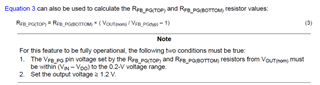
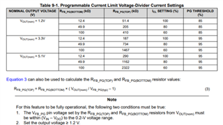
From the datasheet section 9.1.5, the table shows the 1.2V ,3.3V 5V output with their RFB_PG(TOP) || RFB_PG(BOTTOM)

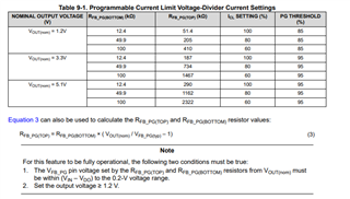
Could you tell me the 0.8V output ,how much value of the RFB_PG(TOP) || RFB_PG(BOTTOM)

And also please help me to know more about ICL SETTING (%)  and PG THRESHOLD (%)

Best regards,
William

  • Hello William,

                          To get 0.8V output please short the FB pin and the OUT pin (RFB_TOP = 0Ω and RFB_BOTTOM = Do not populate). TPS7A80 does not have a PG pin. Could you verify if the correct part has been referenced in this thread? Thanks!

    Regards,

    Srikanth

  • Hi  Srikanth

    Thanks for your reply

    Output 0.8V, short the FB pin and the out pin
    Is the maximum output current 1a in this case?

    Best Regards,
    William

  • Also I have another question, 

    The design goal is that input VIN = 2.5V, output Vout = 1.8V, ICL = 80%
    1. Calculate RFB according to equation 3_ PG(TOP),RFB_ When PG (bottom), VFB_ What should PG (typ) be selected? Is the voltage range 0.19 ~ 0.21, or (VIN VDO) ~ 0.2V?

    2:How is the PG threshold parameter in table 9-1 calculated and determined

    Best Regards,
    William

  • Hello William,

                         The current limit for TPS7A80 is not programmable and it does not have a PG pin. Please verify if the correct part has been referenced in this thread. Thanks!

    Regards,

    Srikanth 

  • Hi experts

    I am sorry that the MPN is TPS7A94 not  TPS7A80 ,please help me to confirm the question above.

    Best Regards,
    William

  • Hello,

             I am looking into this, I will get back to you by the end of the day tomorrow. Thanks!

    Regards,

    Srikanth

  • Hi experts

    Thank you, good night, I will look forward your reply.

    Best Regards,
    William

  • Hello Jiahui,

                       Please find below my responses to your queries beginning with the first one posted on Nov 29th:

    (1) RFB_PG(TOP) and RFB_PG(BOTTOM) do not set the output voltage value. The resistance connected to the NR/SS pin (RNR/SS) sets the output voltage. We have an internal 150uA current source, and the product of this current and RNR/SS sets the output voltage. For 0.8V output, we recommend that a 5.36KΩ resistor be connected to the NR/SS pin. For other output voltage values please consult table 9-3 of the datasheet for recommended RNR/SS values.

    (2) The value of the parallel combination of RFB_PG(TOP) and RFB_PG(BOTTOM) (lets call it RFB_PG(NET)) will determine the value of the current limit ICL. If RFB_PG(NET) is less than 10kΩ, then the current limit assumes its nominal value. If 10KΩ < RFB_PG(NET) < 50KΩ, then the value of ICL equals 80% of its nominal value and lastly, if 50KΩ < RFB_PG(NET) < 100KΩ, then the value of ICL equals 60% of its nominal value. The customer has to decide what the output threshold for PG should be. Lets assume that 85% of VOUT (NOM) has been selected as the PG threshold, then this would require the voltage at FB_PG pin to be VFB_PG = 200mV/0.85 = 235mV. The FB_PG feedback resistor values have to now be selected so that the equation VOUT (NOM) = VFB_PG*(1 + (RFB_PG(TOP)/RFB_PG(BOTTOM))) (Equation 3 in the datasheet) is satisfied, where VFB_PG = 235mV in this example case. 

    (3) As you mention, the design case is VIN = 2.5V, VOUT = 1.8V, ICL = 80%. The PG threshold should also be selected by the customer, lets assume that the PG threshold = 85% of VOUT (NOM). As was mentioned earlier, this would require that the voltage at FB_PG pin to be VFB_PG  = 235mV. From Equation 3 of the datasheet we have RFB_PG(TOP) = RFB_PG(BOTTOM) * ((VOUT (NOM)/VFB_PG) - 1). Here VOUT (NOM) = 1.8V, VFB_PG = 235mV and if we assume RFB_PG(BOTTOM) = 49.9KΩ, then RFB_PG(TOP) comes out to be equal to ~332.3KΩ. Selecting a resistor value close to this, would give you the 85% PG threshold and since 49.9KΩ ΙΙ 332.3KΩ = 43.3KΩ, the criterion for ICL being equal to 80% of its nominal value is also satisfied. RNR/SS = 12KΩ would help set VOUT = 1.8V.   

    I hope this helped provide you more clarity on the FB_PG resistors, ICL and PG threshold. Let us know if you have more questions. Thanks!

    Regards,

    Srikanth

  • HI  Srikanth

    Thanks for your reply.

    Please also help confirm RFB when Vout = 0.8V for TPS7A80 ,RFB_PG(TOP) and RFB_PG(BOTTOM),How should PG (bottom) be configured.

    (To get 0.8V output please short the FB pin and the OUT pin (RFB_TOP = 0Ω and RFB_BOTTOM = Do not populate)
    Is this reply aimed at tps7a80 or tps7a94?)


    At this time, the current limit feature does not take effect, right? So the maximum current is 1A?

    Best Regards,
    William

  • Hello William,

                       Please note that TPS7A80 does not have FB_PG or PG pin. Hence we cannot connect RFB_PG(TOP) and RFB_PG(BOTTOM) resistors. TPS7A80 has the regular OUT and FB pins. Hence to get 0.8V at the OUT pin, you can short the OUT and FB pin (RFB_TOP = 0Ω and RFB_BOTTOM = Do not populate). TPS7A80 does not have the programmable current limit feature. My response on Nov 29th refers only to TPS7A80. 

    Regards,

    Srikanth  

  • Hi Srikanth

    Thanks for your reply.

    I am so sorry,I wanna to know  tps7a94 , I write down incorrectly.

    Please  help confirm RFB when Vout = 0.8V for tps7a94 ,RFB_PG(TOP) and RFB_PG(BOTTOM),How should PG (bottom) be configured.

    (To get 0.8V output please short the FB pin and the OUT pin (RFB_TOP = 0Ω and RFB_BOTTOM = Do not populate)
    Is this reply aimed at tps7a80 or tps7a94?)


    At this time, the current limit feature does not take effect, right? So the maximum current is 1A?

    Best Regards,
    William

  • Hello William,

                          "To get 0.8V output please short the FB pin and the OUT pin (RFB_TOP = 0Ω and RFB_BOTTOM = Do not populate)". This is aimed at TPS7A80. 

                    RFB_PG(TOP) and RFB_PG(BOTTOM) do not set the output voltage for TPS7A94. They set the PG threshold point and current limit, which are both determined by the user. TPS7A94 does not have a FB pin, hence there is no need for RFB. I am not sure I understand what you mean by PG(bottom). Could you clarify this? The PG pin can pulled up to VIN using a pull-up resistor (RPG) of value 10KΩ ≤ RPG ≤ 100KΩ. 

                     I have explained how to select the values of RFB_PG(TOP) and RFB_PG(BOTTOM) for a particular PG threshold point and a particular ICL in my earlier post on Dec 2 :  https://e2e.ti.com/support/power-management-group/power-management/f/power-management-forum/1057455/tps7a80-0-8v-output/3917481#3917481. In the same post I have explained that a 5.36KΩ resistor be connected to the NR/SS pin to get the desired 0.8V output voltage. If there is some section of the post that is causing a confusion, please let me know, I can try explain it better. Thanks!

    Regards,

    Srikanth 

  • Hi Srikanth 

    Use RFB_ PG(TOP) and RFB_ PG (bottom) configures ICL. When Vout = 0.8V, whether it follows the same principles as Vout = 1.2V, 3.3V, etc. In the figure below,

    what does Note 2 mean?

    Best Regards,
    William

  • For  TPS7A94

  • Hello William,

                          The programmable current limit feature would work only when VOUT ≥ 1.2V. The PG functionality would however work even when VOUT = 0.8V. You are correct, at this output voltage (VOUT = 0.8V), the current limit would assume its nominal value. Thanks!

    Regards,

    Srikanth