Other Parts Discussed in Thread: UCC256404, UCC25640EVM-020
Dear Sir/Madam,
I have purchased and tested the evaluation board PFCLLCSREVM034, its performance is very good. After reading the user guide and datasheet of the UCC256404 and using the design tool UCC25640x Design Calculator Rev4.0, I have some questions regarding the resonant capacitor and resonant inductor and I hope you can give me some advices.
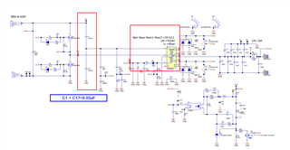
1) According the design procedure in the datasheet and the UCC25640x Design Calculator Rev4.0, I know the resonant capacitor value is 0.030uF = 30nF. But I can't find this capacitor in the circuit. Maybe this resonant capacitor consists of many capacitors connected in parallel or series? Could you identify it for me? My reference is schematic of PFCLLCSREVM034.
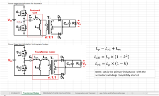
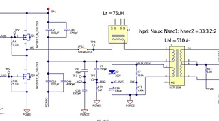
2) The detailed information of transformer is not listed in the user guide. The only information I got from schematic is turn ratio = 33:3:2:2 and LM=510uH. I can't find out the value of leakage inductor. This is another question in the point 3 below.
3) Regarding the resonant inductor. I would like to know should we consider about the leakage inductor of transformer? For example, if the calculated resonant inductor is 100uH, and the leakage inductor of the transformer is 20uH, should I use a 80uH inductor or still a 100uH inductor?
Thank you for your answer.