This thread has been locked.

If you have a related question, please click the "Ask a related question" button in the top right corner. The newly created question will be automatically linked to this question.

LM5085: Big voltage drops when powering servos

Part Number: LM5085

I am using a circuit generated by Power Designer in a circuit board intended to drive several hobby-type servos, for use in robotics teaching labs.

The problem I am having is really big voltage drops, presumed to be associated with the inrush current of the servos. Since they are digital servos, a big transient voltage drop can be enough to make the internal controller brown out, and the servo fails to move properly.

I am stepping down from 24V to 6V, and viewing the output on an oscilloscope shows the voltage can drop as low as 2.7V with a single servo (TowerPro MG996R), and I need to drive at least 4 of them.
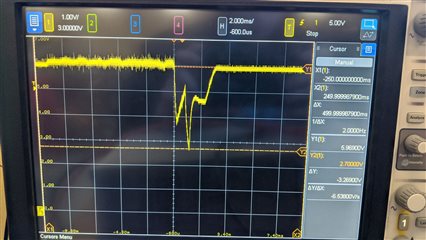

Adding more capacitance helps a bit, but nowhere near enough. My feeling is that the source of the problem must be more fundamental than that, but, not being remotely a power design expert, I'm at a loss to know what could be going wrong and how to fix it. I'm also under intense time pressure and need to find a solution within the next day or so. I would hugely appreciate any advice that you could offer Slight smile

  • Hi,

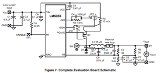
    Your application appears to follow a similar typical application shown in the datasheet Section 8.2

    Your inductor value is significantly smaller than the 15uH. Depending on the output current transient from the servos, the 4.7uH inductor will be derated and could impact transient performance.

    Perhaps the L (inductor) and Cout (output capacitance) combination you have results in a situationally operational design but is not as robust with load transients. 

    Since you've tried to increase the output capacitance, the next step is to equalize the inductor to a 15uH similar to the example circuit and retest transient performance.

    Regards,

    Jimmy

  • Thank you for this Slight smile

    Unfortunately, it did not resolve the issue, because increasing the inductor to 14.1uH resulted in a large voltage drop at the output (from the desired 6V down to about 2.5V). I observed some very strange behaviour whereby applying an oscilliscope probe to the switch node whilst drawing current from the output was somehow able to 'knock' the circuit into outputting the correct voltage, but I never managed to get to the bottom of why this was happening, nor was I able to reproduce the behaviour with an RC network instead of a scope probe.

    I ran through the calculations on the datasheet for my application (24V nominal Vin, 12-24V Vin range, 6V output, 10A max output) and arrived at similar component values to those output by the TI Power Designer. I wasn't able to figure out which I would need to change (if any) to account for a larger inductor. It should be mentioned that I increased the inductance by adding three 4.7uH inductors in series, since I didn't have time to order a 15uH one, so perhaps that was part of the issue.

    At the moment I'm having to proceed with a crappy workaround whereby I set the circuit to a higher Vout and place an LDO on the output to handle some of the transient demand, purely because of the time pressure to get something vaguely working. This is highly unsatisfactory, and I would really like to understand why the circuit is behaving as it is, even if I acquire this knowledge too late to apply it to my current design. I'd be very grateful for any further insight!

    Thanks a lot

    Mike

  • Hi Mike,

    What is the ESR of the bulk output capacitor in your design? Perhaps that is too low and causing regulation issues since this device needs some amount of ripple at the FB pin to properly have regulation. 

    Refer to Figure 25  and noticed how they have three additional components (R3, C1, and C2). Can you try using these values in your circuit as well? These components are also on the EVM. I would suggest copying the exact component selections here to test for regulation. 

    If that is not desirable then perhaps you can add an AC coupling capacitor between VOUT and FB (see Figure 5 in User's Guide). 

    Regards,

    Jimmy