This thread has been locked.

If you have a related question, please click the "Ask a related question" button in the top right corner. The newly created question will be automatically linked to this question.

TPS62912: Output High - Inductor Failure

Part Number: TPS62912

Hi TI Support,

We recently fabricated 10 boards using a new design with TPS62912.  The build is experiencing a high failure rate.  The design came off Webench.  See specs below.

We saw 4 boards with output high (40% failure which is a lot).  The failure is related to 2.2uH Pulse Electronics inductor.  Replacing the inductor with a new unit (same Pulse P/N) fixes the high output issue.  Removed inductor shows abnormally low inductance.  This inductor was called out by Webench.

We are not sure if the inductor failed due to quality issues or the inductor failed due to IC controller issues.  After inductor was replaced, the switch node waveform looks normal; however the power up sequence (softstart) shows some unexpected behavior.  We are seeing double pulsing.  See attached scope captures.  On one TI Eval board for TPS62912, the startup waveform is different.  It does not double pulse and has uniform pulse shape through out the entier softstart duration until it reaches steady state (duty cycle = Vo/Vin).

Questions:

1. Is the observed double pulsing abnormal? 

2. Is this (above) an indication of pending controller failure or would lead to inductor failure (excessive high peak current)? 

3. Are there any known limitations of the TPS62912 part running at 2MHz? 

4. Should we back off to 1MHz for a more robust design?

5. Possible cause for inductor failure?

Regards,

John

DC/DC Converter Spec:

Controller: TPS62912

Vout: 5.0V

Iout: 2Amp max (actual loads in the 0.5A range)

Vin: 8V to 16V

Switching freq: 2MHz

Inductor: 2.2uH (called out by Webench)

Inductor Manuf: Pulse

Inductor P/N: PA4332.222NLT

Attached scope captures:

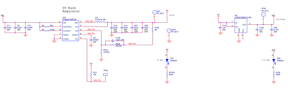
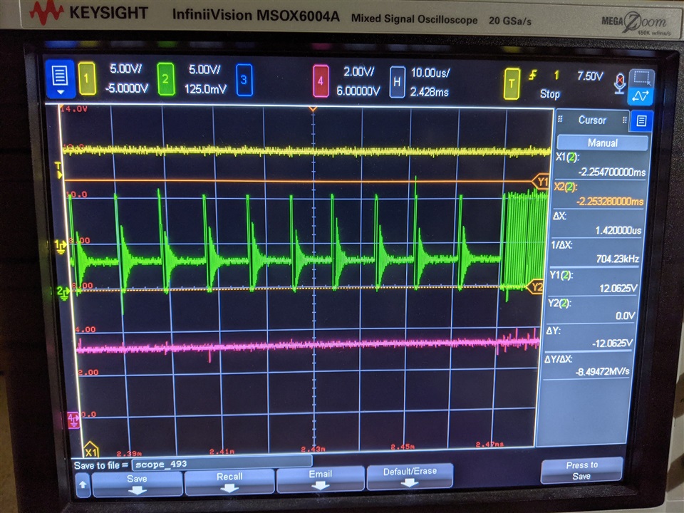
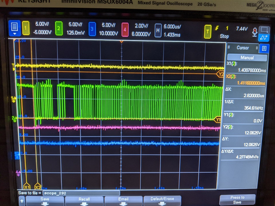
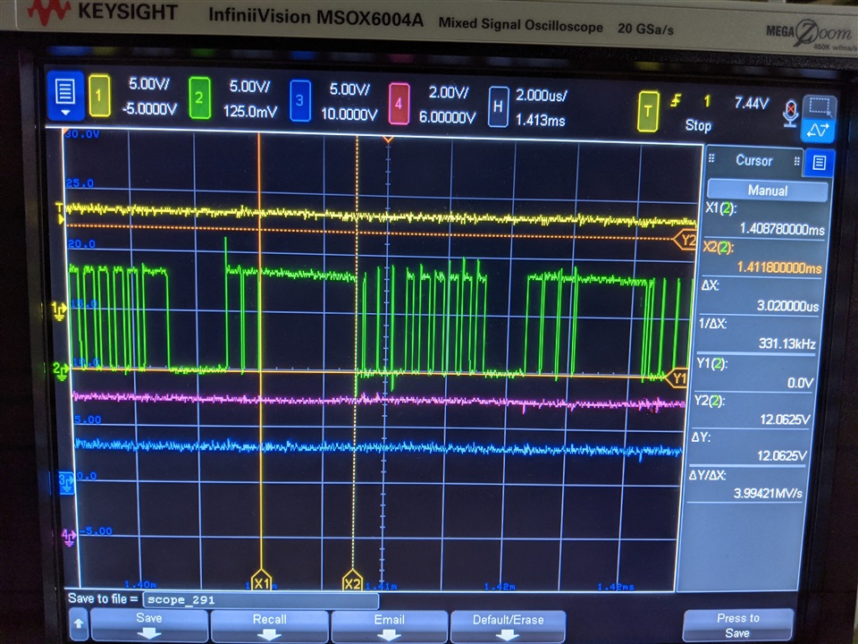
1. customer's failed board with 5Vout high at 5.9V, 2.2uH inductor replaced, Vout=5V, Vin=12V, light loads < 0.5A, scope capture shows switch node double pulsing on power up (start-up): green channel

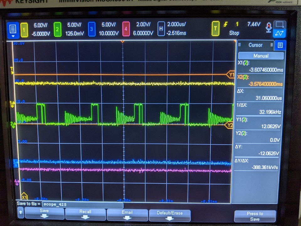
2. TI Eval board (TPS62912 EVM-077, SN:670-020-002-1) switch node, ramp up, no double pulsing, board Vin=12V, Vout=3.3V, no load, 2MHz: green channel

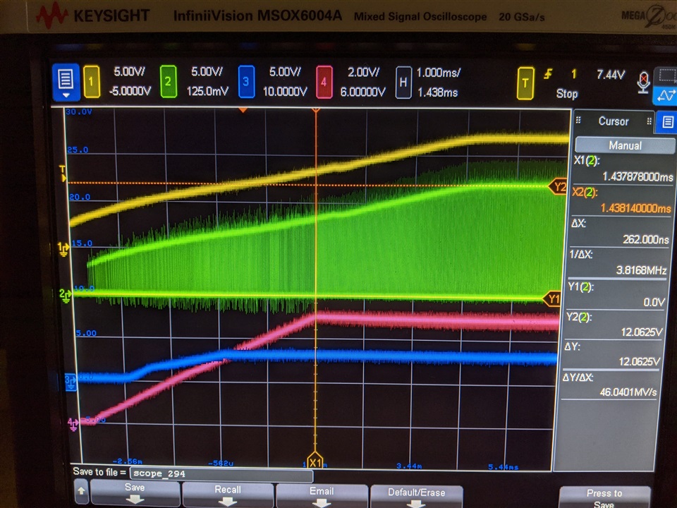
3. customer schematic based off Webench design

  • Here are more scope captures for a repaired board (high output, replaced bad Pulse 2.2uH inductor).  Ramp up switch node pulses look bizarre.  Switch on pulses do not have  any off time between pulses.  In addition there are group of pulses without off time in between.  Inductor ringing should be observed when switch is off during soft start period.  Is TPS62912 damaged?

    green ch: switch node,

    pink ch: 5Vout

    yell ch: Vin

    1.  storage_sn011_switch_node_ramp_up_on_time_with_no_long_off_times_1.jpg, green trace - switch node, 1msec/div

    2.  storage_sn011_switch_node_ramp_up_on_time_with_no_long_off_times_2.jpg, green trace - switch node, 5usec/div

    3.  storage_sn011_switch_node_ramp_up_on_time_with_no_long_off_times_2.jpg, green trace - switch node, 2usec/div

  • Hi John

    Nancy is looking into this and will feedback to you.

    BR

    Ruby

  • Hi John,

    Review the schematic and I think your input caps may be too small with 2x6.8uF. Others looks ok. Could you send us the PCB layout if it is possible?

    My email address: nancy_zhang@ti.com. So we can debug offline.

    You build total 10 boards, only 4 boards have this behavior. Are all other 6 boards working properly?

     1. Is the observed double pulsing abnormal? 

    Nancy: it is abnormal. Is this double pulse with bad inductor? or good new inductor? For bad inductor, how bad is the inductor value? 1uH or lower?

                Did you contact Pulse about this inductor failure? 

                What is the test condition for your first two waveforms, the switching node waveform is incorrect. TPS62912 should operate in fixed frequency PWM                mode down to no load and switching node should not have any ringing. Also the switching frequency looks not  to be 2.2MHz.

                Please double check if there is anything wrong on the board.

    2. Is this (above) an indication of pending controller failure or would lead to inductor failure (excessive high peak current)? 

    Nancy: The behavior of waveform does appear that there is some damage. Could you swap a new IC to confirm if the controller was damaged? The                           controller should not lead to inductor failure. But the inductor may cause controller damage. So what is inductance and DCR value for failure inductor?

    3. Are there any known limitations of the TPS62912 part running at 2MHz? 

    Nancy: There is no known limitations of TPS62912 part running at 2.2Mhz for 8V-16Vin, 5Vout with normal 2.2uH inductor.

    4. Should we back off to 1MHz for a more robust design?

    Nancy: find the root cause first. 1MHz may have a higher ripple.

    5. Possible cause for inductor failure?

    Nancy: Please contact Pulse for root cause of inductor failure. They are experts.

    6. Could you please change input cap from 2x6.8uF to 2x10uF or 2x22uF? And make sure these two caps are as close as possible to IC pins. Poor PCB        layout may cause unstable system.

    Please email me if needed. We can debug it offline.

    Thanks,

    Nancy

  • Hi Nancy,

    Thanks for the quick response.  Yes, I will send you the pcb layout for review.  We basically followed TI's eval board layout, almost identical with minor mod to address DFA and DFT (design for assembly and test) issues.

    My comments below.  I will email you directly for more discussions.

    Rgds,

    John

    0. Yes, other boards have correct 5V output but during power up or softstart duration, we are seeing anomalies at the switch node. 

    1. We just got hold of Pulse.  We requested Pulse to perform failure analysis on the failed inductors. 

    Test condition for first two captured waveforms: power up sequence or ramp up stage.  Switch node after soft start looks normal - on/off durations with no ringing (text book shape for PWM pulses).

    2.  From our EE staft member: "I found anywhere down to 100-200 nH instead of 2.1-2,2 uH. The quality factor is dropping substantially as well (at 100 kHz, it could drop below 5, while good parts show a Q = 17-18)."

    DCR << 1.0ohm

    6.  Yes input caps are placed in very tight loop similar to TI eval board.  Will try adding more capacitance at input.  Will increasing input capacitance improve stability or eliminate double pulsing and other anomalies during soft start phase?

    For input ceramic caps, (after factoring in drop in capacitance due to applied DC voltage), the physical size can be very large.  This is the reason for keeping total to 2x6.8uF/35V.

  • Hi John,

    I received your email and will reply you over email. I will close this post.

    Thanks,

    Nancy