This thread has been locked.

If you have a related question, please click the "Ask a related question" button in the top right corner. The newly created question will be automatically linked to this question.

TPS562202S: Changed inductor, regulator stopped working

Part Number: TPS562202S
Other Parts Discussed in Thread: TPS562202

Hi,

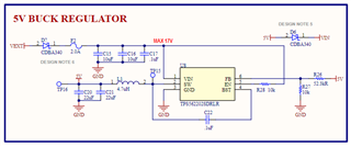
I designed a 5V buck regulator using the TPS562202S IC, which I use to step down a 10 V input. I followed all the design guidelines for this first design, using the recommended component values from table 9-2 of the datasheet, the inductor being this Wuerth Elektronik 74437368047. The circuit seemed to work OK, with a 5V output and about 200 mV ripple at no load and 3.33 kHz switching frequency. Good enough for my uses. Here is the schematic:

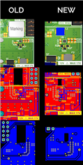
I then swapped the inductor L1, because the original Wuerth was simply too large for my design. I selected this Abracon AMDLA4020S-4R7MT, since it was much smaller and had a high enough saturation current of 4.5 A and a current rating of 3 A. The only difference (that I could see) was that the DC resistance was 70 mOhm (max), vs the 15.5 mOhm (max) of the Wuerth 74437368047. I didn't think that would be a problem. However, this circuit no longer works. Here is an image comparing the two, this is a 2-layer PCB.

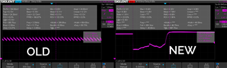
Here is an image comparing the output. The old design uses the Wuerth indcutor, the new one uses the Abracon. The old design works, the new one just does not: it is not constant. Sometimes it reaches 2 V (instead of 5 V), then the output matches the input voltage, then it switches around randomly. So, something is definitely wrong.

Questions:

1. Taking into account that both schematics are identical, with only the change of the inductor selection, can anyone notice any errors between the old layout (which works) and the new layout (which doesn't)?

2. The one thing I am noticing now, is that the Abracon inductor reads as "designed for switching frequencies between 100 kHz and 5 MHz" in the datasheet. The regulator does not seem to reach 100 kHz until a small load is applied (say, about 50 mA), and it stays at frequencies below 10 kHz at no load. Could the inductor be the problem? Any ideas?

Thank you in advance for your support.

  • Hi, Dan !

    1. It suggests you try to solder the new inductor ( Abracon ) into the old layout board, if the problem is caused by the new inductor, it may also not work with the new inductor in old board. If it works well, the problem may be caused by the new layout board.

    2. Please provide the waveform  of the inductor current, the voltage between SW and GND and the output voltage of new boards with the new inductor for further analysis. It is better these waveforms shown in one screen.

    3. For your second question, the lower frequency is usually determined by the saturation current. In normal PWM control, the peak-peak value of the inductor will increase with the increasing of the turn-on time or turn-off time, which corresponds to the frequency. In our TPS562202, it uses the D-CAP2 control. In low load condition, it operates in DCM Eco mode, the up time and the down time of the inductor is same as that in normal frequency 580K. So it may not be the reason of problem.

    BSR MV

    Shuai

  • Hello Shuai,

    Thank you very much for your prompt response. Some answers:

    1. I moved the new inductor (Abracon) into the old PCB, and the regulator worked. So this confirms the inductor is not the problem.

    However, I then swapped the original Buck IC in the OLD PCB for an identical, new IC, and the regulator did not work any more. I think this might mean that the IC is becoming damaged when soldered. I used a soldering iron at 300°C, applying heat for only a few seconds on each side. I also attempted the same process with a heat gun, but same results. With a new IC soldered by me, the regulator does not work any more. The only PCBs that work are the ones I received from the PCB manufacturing house, already assembled.

    I do not doubt my soldering abilities, I was very careful, but something is off. I will investigate this further, maybe attempting to solder at a lower temperature (I was using 300°C on the soldering iron), and will report back.

  • Hi Dan!

    Please double check if the position of pin of the IC is correct. 

    Shuai