This thread has been locked.

If you have a related question, please click the "Ask a related question" button in the top right corner. The newly created question will be automatically linked to this question.

LM74610-Q1: Alternative application

Part Number: LM74610-Q1

Hello,

We have already purchased a bath of LM74610-Q1, but the testing showed that this IC does not exactly fit our need. The problem is that we cannot accept it's 2 modes of operation. We need the controller to keep the MOSFET turned on - because we are using it on a low voltage 2,5-5,5V line.

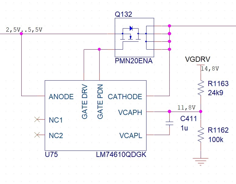
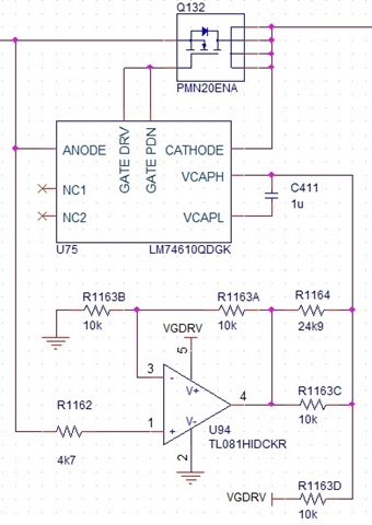
I've been trying to bias the Vcap pins to get the MOSFET constantly turned on. I came up with the attached schematic. The MOSFET stays turned on and the reverse blocking functions properly. I calculated the resistor divider to always have the 6,3V between VcapH and VcapL. To achieve this for input (anode) voltage of 5,5V, I got 11,8V for VcapH.

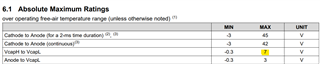
The question is if the IC will function normally with 11,8V at VcapH (through a 25k serial resistor)? Or is there a huge stress inside and it will burn sooner or later?

Thank you for your kind answers,

Jacek

  • Hi Jacek,

    Can you please help me understand the following,

    1. Have you already tested the modified circuit ? 
    2. What is the voltage tolerance of VGDRV rail ?
    3. Does VGDRV vary with Vin (Anode voltage) ?
    4. Does your application only require input reverse polarity protection ?
  • Hi Praveen,

    1. Yes, I've tested this circuit. The MOSFET is constantly turned on, and the reverse voltage protection works. When I short the output (cathode) to any higher external voltages, the MOSFET is turned off. So it meets my needs.

    2,3. VGDRV is very well regulated, it is generated by a boost DC-DC converter. It can be considered as a constant 14,8V voltage source.

    4. Yes. The only function I need is the "Ideal Diode" function (with the maximum reverse voltage of 30V).

    As I've measured, the VCAPL voltage is always close to Anode voltage.So when Anode voltage is 5,5V, we get VACPH-VCAPL=11,8-5,5=6,3V. As I understand this is the condition to keep the MOSFET turned on.

    But when the Anode voltage is turned off (0V), VCAPH-VCAPL=11,8V. This brings my doubts, because the datasheet says that VCAPH-VCAPL max is 7V. As I do not know the internal structure of the IC, I do not know if these conditions cause stress.

  • Hi Jacek,

    As you mentioned, the Abs Max rating of VcapH to VcapL  is 7V. When the Anode voltage is less than 4.8V, the VcapH to VcapL voltage will be > 7V. 

    Violation of this spec can damage the device. So in the condition when Anode voltage = 0V, VCAPH-VCAPL=11.8V, the device will get damaged. 

  • Hi Praveen,

    Thanks for your answer.

    I came up with a bit more complex solution. The Op-Amp averages Vanode and VGDRV in certain proportions so that VCAPH-VCAPL is almost 7V for Vanode=5,5 and 6,1V for Vanode=0V. So I believe this max rating is now safe. Can you have a look at the schematics and see if you have any other comments?

  • Hi Jacek,

    Let me review the schematics and get back to you by early next week.

  • Hi Jacek,

    What would be the output of op-amp when there is input reverse polarity and ANODE pin ? Have you simulated this condition ? Please share the TINA simulation file for my reference.

    If you really wish to go ahead with this circuit, I recommend the following before going ahead,

    1. You will have to verify this circuit under all system conditions including transients 
    2. We need to check with design team if there will be any long term reliability issue to the IC as we are forcing current into the charge pump externally. I can help you with this once you confirm. 
  • Hi Praveen,

    I am waiting for the Op-Amp samples, they are on their way. As soon as I get the Op-Amp, I will assemble this circuit into my board and do the tests in all the conditions. If this goes well, I will get back to you with the test results and with the long term reliability matter.

    For now I did not do any simulation, only calculations.

    I think Christmas time might disrupt the work on this case, as my company is closed for 2 weeks after. If so, I will get back to you after the 9th of January. If I manage to test the circuit before Christmas, I will send you the results and the confirmation to check with the design team.

    Thanks for now and Merry Christmas :)

  • Hi Jacek,

    Thanks for the update. For now I am closing this thread.

    Once you are back to office, we can continue our discussion in the same thread or you can create a new thread.

    Happy Christmas!!