This thread has been locked.

If you have a related question, please click the "Ask a related question" button in the top right corner. The newly created question will be automatically linked to this question.

TPS63020: TPS63020 Feedforward network value discrepancy

Part Number: TPS63020

Hi,

I appreciate this is an old part, but I'm looking for clarification on the suggested 'fast transient' network that can be added to the feedback network.

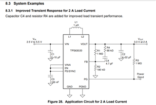
From TPS63020 Datasheet - values are 68kohm and 4.7pF (estimated zero = 33kHz, pole = 150kHz)

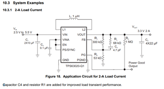
From the TPS63020-Q1 datasheet - Values remain the same for the feedforward network, but R1/R2 is much lower affecting zero/pole response

Estimated zero=100k, pole=271kHz

Is there a vast difference in between the two parts or is there an error in documentation? Or something else? 

Please can you advise which network is correct?

Thanks, Josh

  • Hi  josh,

    it is caused by different value of R1 and  R2. 

    Regards

    Tao

  • Hi Tao,

    Thanks for getting back to me.

    Yes, the difference in zero/pole is caused by the different R1/R2 values, however if both of these parts are identical, why such a big difference in compensation setting?

    In other words, if I wanted to use either part in my design should I also change the R1/R2 values?

    My thoughts are that only one zero/pole setting is correct and should be the same for both part numbers. 

    Also, let's say that I don't want a 3.3V output, but instead a 2.5V output.

    If I knew which zero/pole setting was correct, the 68kohm & 4.7pF could be easily recalculated to provide the same response as shown in the datasheet.

    However, which zero/pole setting is correct?

    1. zero 33kHz, pole 150kHz

    2. zero 100kHz, pole 271kHz

    Obviously I will need to check stability on the hardware, but it'd be good to get clarification on this before they are manufactured.

    Any help appreciated!

  • Hi  josh,

    that is a good point.

    I agree that there should be only one zero/pole setting but not two different ones for TPS63020 and TPS63020-Q1. But i think feeddorward is not  necessary and you can reserve a cap in parallel with R1 only.

    For TPS63020-Q1, it is designed for Auto and small resister divider is required for complex application environment

    Regards

    Tao