This thread has been locked.

If you have a related question, please click the "Ask a related question" button in the top right corner. The newly created question will be automatically linked to this question.

TPSI3050-Q1: Schematic review & PSPICE simulation error.

Part Number: TPSI3050-Q1
Other Parts Discussed in Thread: TPSI3050

Hi,

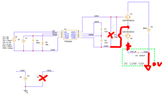
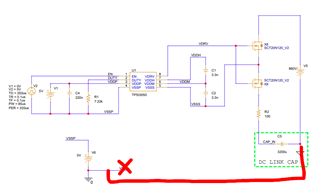
The customer wrote a schematic of DC LINK PRE-CHARGE.

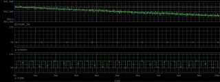
An error occurs as a result of the PSPICE simulation.

1. Please review the schematic.

2. Please guide me on how to improve simulation error.

TPSI3050-Q1_Schematic.pdf

211214 ERROR CODE.TXT

  • Hi Cho,

    Thank you for sharing this! Our team will be glad to review the schematic by this afternoon. For the simulation error, can you confirm if this is the same or different error as your last thread?

    https://e2e.ti.com/support/power-management-group/power-management/f/power-management-forum/1059148/tpsi3050-q1-pspice-transient-model-dwz-package-one-shot-enable-error/3925796#3925796

    Thanks!

    Alex

  • Hi Cho SR, 

    Thank you very much for reaching out with these questions. 

    1- The following recommendations in your schematics would help your system to reach convergence and to operate as expected. 

         - Remove the loading capacitor from VDRV since you are already loading the driver with the FETs

         - Connect VSSS to the source of your FETs since you need to create a potential difference from Gate to Source in order to drive b2b FETs.

         - Let's add a series resistor to your link capacitor to help the convergence 

         - Let's add a ground to you battery to help with convergence issues 

         - Let's eliminate the battery connection from ground to VSSS to eliminate any further concerns 

    2- I noticed that you are having convergence issues. We can also relax your convergence variables by using the auto-converge in the simulation configuration options. 

    I believe that these recommendations should produce the proper output in your simulations, but let me know if you have any further troubles. 

    Let us know if this answers your questions. 

    Sincerely, 

    Francisco Lauzurique. 

  • Hi Alex,

    The last thread error has been resolved.

    It's another error, and I'll refer to Francisco's answer.

    Thank you.

  • Hi Francisco,

    The customer revised the schematic map and tested it.

    TPSI3050-Q1_Schematic_20211215.pdf

    However, the capacitor is not charged and there is no signal from the VDRV pin.

    VSS connection was removed and tested.

    The results are the same.

    It's the same result.

    Updated Project file : 

    211215.zip

    en.sct20N120_spice.zip

  • Hi Cho SR, 

    Thank you very much for all this information. 

    I am currently experiencing some licensing issues with my PSpice. As soon as I get over these issues, I will open these files and provide more detailed feedback. 

    To keep the debugging effort here:

    1- Disconnect the FETs from the driver and see if the driver is able to toggle VDRV high and low without load (place a 10nf for loading). I am recommending this because I see you are using a very small capacitance for the CDIV1 and CDIV2. These capacitance values should be about 10x your Cg. I noticed in the datasheet  of the FETs you are using that Qg is about 45nC, therefore, you will need to increase these capacitors. I would recommend using 1uf for C1 and C2. If you get to see VDRV pulses, then connect it to the FETs.  

    2- Thank you very much for following the previous recommendations. I would recommend eliminating the connection to VSSS and for faster convergence, I would recommend connecting primary ground to the battery ground while testing these simulations.  

    Let us know if this response answered your questions. 

    Sincerely, 

    Francisco Lauzurique 

  • Hi Cho SR, 

    Was the customer able to simulate the circuit with the previous recommendations? Let me know if there is further help needed with these simulations.

    Best, 

    Francisco Lauzurique  

  • Hi Francisco,

    Sorry, the customer's problem has not been solved.

    However, the thread will be terminated as the time is being delayed.

    When I receive feedback from the customer, I will ask a connected question.

  • Thank you very much for the reply Cho SR. 

    I will go ahead a close this thread.