This thread has been locked.

If you have a related question, please click the "Ask a related question" button in the top right corner. The newly created question will be automatically linked to this question.

LM5106: LM 5106 problems

Part Number: LM5106
Other Parts Discussed in Thread: LM5102

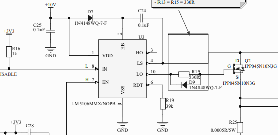
We are having problems with using LM5106 half bridge driver IC, it works most some of the time. but there are other times where  we are seeing a lot of failures and excess IC temperatures. We need to understand what we are doing wrong to cause this problem so that it can be rectified as soon as possible.

  • Hello Bill,

    Can you provide a bit more details about your system? Based on what you said about excess IC temperatures, could you provide the VDD, switching frequency, and what you are driving (FET or capacitive load)? The reason I ask for these, is that the rough power dissipation of the device is P=VDD*Fsw*Qg so we could calculate how much we would expect the IC to heat up in your system. If you are willing, a small part of your schematic showing the driver and the supporting components could also help determine what is going wrong.

    thanks,

    Alex M

  • Hi Alex,

    Sorry about being vague on the forum but I have to try and protect the companies products.  OK to give you a little back ground the design has been though several different people and has been modified too along the way.  I have been told to sort it out by my boss who wants an easy fix!!!

    if it was mine design I would not be using this IC at all, as I think its wrong for the job. I would just drive the low side conventionally.

    I fully understand that the LM5106 is been used in a none ideal way but it landed in my lap...............

    as you asked VDD is 10V

    Fsw = is 0Hz as I believe they are just turn the fet on and off occasionally 

    the FET being used is a IPP045N10N3G switching only on the low side

    I can only include a very small part of the schematic due to it being a forum but I do understand with out a diagram its almost impossible to work out what they have done wrong.

    If you need more info please just ask and Many thanks for your reply today

    Kind regards

    Bill

  • Hello Bill,

    Thanks for providing these details. Based on the VDD and switching frequency, there shouldn't be very high power dissipation in the device. If I understand correctly, you keep IN low and toggle the lowside by toggling enable? I made a simulation and that method appears to work fine. I don't see anything in the design that is definitely a problem. Here's a few things you could try on your boards to see if it helps:

    1. You can remove D7 and C24, these are used for generating the high-side bias, which you are not using.
    2. You can try increasing the VDD capacitance, 0.1uF is pretty small.
    3. You can try using a smaller resistor for the gate; R15 is 330 ohms which is really big for this. Usually gate resistors are between 1-50ohms. 
    4. You may be able disconnect the "LS" pin from the drain of the FET. If they are connected by a trace on the board you may be able to lift the package's leg to disconnect it. I'm not sure what kind of voltage you are applying to LS, but that pin is not needed for the application you are doing and is a possible failure point. 

    Sorry to send so many suggestions. I'm not sure what the problem is so hopefully at least one of these helps you out. If none of these help, feel free to reply again and we can consider some more options. Lastly, I do think you would have an easier time using a low-side driver for this application like you said, but there is no reason why a half-bridge shouldn't be able to do this. I think most of our drivers with separate Lin and Hin pins would be easier to use though. Something like the LM5102 has very similar specs and is pin-to-pin but will allow the independent control. 

    Best of luck,

    Alex M.

  • Hi Alex,

    Sorry for the delay, busy morning here.  Thank you for your rely that's good of you!!

    OK with regards to the list you suggested 

    • I  pre-removed C24 and D7 for the reason that you had point out 
    • I have keep VDD 0.1uf cap in circuit for filtering of the LM5106 but I have added an additional 22uF buy tagging over D7.
    • I have adjusted the gate turn on resistor down to 22R 
    • I have lifted the LM5106 and cut the track completely.  

    We will be testing very soon I will let you know how it goes !!

    Thank you again for you help 

    Kind regards

    Bill

  • Hello Bill,

    Good luck with the test. If you do see issues, could you provide some scope captures of EN, IN, and LO so we can see if there is anything strange about the waveforms? If you don't see any issues then there is no need.

    best of luck,

    Alex M.