This thread has been locked.

If you have a related question, please click the "Ask a related question" button in the top right corner. The newly created question will be automatically linked to this question.

TPS3850: Voltage monitor, manual reset and watchdog by TPS3850

Part Number: TPS3850

Hi,

I'm using TPS3850G50 to monitor a 5 V voltage rail and a watchdog timer from a RPI board; I must also provide a manual reset switchbutton.

Under-/over-voltage condition, manual reset and watchdog timing fault must all activate the same output signal to the RPI.

The requested watchdog timing is about 1.0-1.2 s; reset duration is requested to be more than 2 s.

This is the scheme I designed:

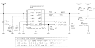
Pin SET1 is enabled high by RPI once the watchdog timer is ready.

WDI windows is set to 0.9-1.6 s by CWD NC and both SET0 and SET1 high.

WDO and RESET outputs are connected together and OR-ed, as they are both open-drain outputs.

WDO (reset) timing is set to 3.2 s by CRST cap = 1 uF.

Currently my issues are:

  1. WDI is not working: I suppose this is because GP10 output has 3.3 V max level, while WDI min is required to be 0.8 x Vdd = 4 V; there I should add a level translator;
  2. the manual reset is not working: when I close switch button S2, the voltage at SENSE pin goes down to 4.5 V as expected by the R1/R6 divider, which is below Vdd - 4% = 4.8 V, but this does not trigger the RESET pin.

Any idea about it?

Thank you in advance

  • Hi Francesco,

    From the looks of your design, there is nothing glaringly out of place. 

    Is it possible for you to isolate the issues one at a time and test them? For example disabling the watchdog, connecting the WDI pin to either VDD or GND, and then trying the MR pin.

    If this is possible, please share any results of this.

    Jake

  • Hi Jack,

    thanks for your kind reply. Following your suggestion, let's try to isolate the issues one a time, investigating first the voltage monitor.

    [This message has been edited after checking a second board].

    That's the default voltages at power-on (all constant, no variation in time, switch S2 open):

    1 VDD 4.95 V
    2 CWD (open) ~0 V
    3 SET0 4.95 V
    4 CRST ~0 V (after a few seconds)
    5 GND 0 V
    6 SET1 0 V
    7 WDI 0 V
    8 WDO 4.95 V
    9 RESET 4.95 V
    10 SENSE (S2 open) 4.95 V

    Due to SET0=1 and SET1=0, watchdog is supposed to be disabled, only voltage monitor is expected to work.

    When I close the S2 switch, voltage at SENSE pins drops to 4.5 V, surely below the nominal VIT-(UV) threshold 5 V - 4% -0.8% = 4.76 V: RESET pin does not falls to 0 V as expected.

    Even if I manually force the SENSE pin to GND, the RESET output does not activate.

    Hope you can help me understanding what's happening. In my opinion, it makes no sense investigating further the watchdog dynamic, until the static behaviour it's not clear.

    Thanks in advance

  • Greetings - Our team will respond to you after 1/3/22. Thank you.

  • Hello,

    Just want to make sure that you have tested this with a second board, and the results are exactly the same?

    Also, where did you procure these parts from?

    If possible, can you send me a photo of the top marking. And also a photo of the label on the tape and reel, if you purchased a reel of parts.

    Also, if you have a chance to test, could you check to see if there is a voltage drop across R10. Also, if you can, disconnect any additional circuitry on the RESET_B output pin see below:

    Jake

  • Hi Jake,

    I confirm I have testes two boards with similar results. However, from gerber I've found some errors in the footprint of TPS3850, therefore I'm preparing a new board with correct footprint. I'll update here once I can repeat the tests.

    Btw, the TPS3850 were purchased from Farnell, so I don't expect any fake component here.

    Thanks

    Francesco

  • Hi Francesco,

    Okay, thank you for the updated regarding the source of the components.

    And yes please post the update with the tests after the update is complete.

    Jake