This thread has been locked.

If you have a related question, please click the "Ask a related question" button in the top right corner. The newly created question will be automatically linked to this question.

LMR14050: Kindly suggest Supply Voltage and Current to choose the SMPS/Power Adapter.

Part Number: LMR14050
Other Parts Discussed in Thread: SN65HVD73, LM61440, , LMR36520AEVM

Hi,

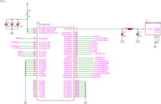
We are using LMR14050SDDA, Schematic as shown below. We need to select the power adapter to supply for LMR14050SDDA. We also need to mention the supply Voltage range and Current on the user manuals.
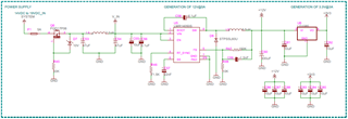
Power Tree:

We are having 12V@700mA load, supplying 12V to 3.3vdc regulator and 3.3V having 1A load. please see the below power tree.

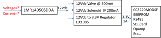
1. Kindly advice the Supply Voltage range and Current for LMR14050SDDA.

Thanks and regards,

Naveen K

  • LMR14050SDDA is 4v to 40V input voltage with 5A loading capacity. so 14V to 19V DC in should be ok in SCH. 

  • Hi Elena,

    Thank you for the information.

    I want to know the possible input ranges for the given load(Power Tree). Kindly advise for individual query.

    1. As per the schematic and Power tree, For 12V output will work fine with input supply range 13V to 40V? What will be the required input supply Current for LMR14050SDDA?

    2. How to calculate the LMR14050SDDA load current? because we using two different load voltage. one is 12V at 700mA load and second is 3.3V at 1A load. So, what will be the actual load for  LMR14050SDDA?

    Thanks and regards,

    Naveen K

  • hi, NAveen,

    LMR14050SDDA could handle no higher than 40V input voltage source , the current is cal by Vout 12V *Iloading/Vin (like 14V to 19V) , 

    LMR14050SDDA load current should be all the current together, like you have a 700mA +LDO3.3V*1A/12V, remember to leave some margin for it 。 max current for LMR14050SDDA is 5A. 

    Elena


  • Hi Elena,

    Thank you for the information.

    This discussion will be helpful to recommend our product user to use the right power supply spec ranges accordingly. Also we need to mention on User manual, specification.

    1. If 12V having 700mA Load and 3.3V having 1A load, Total load for LMR14050SDDA will be 0.975 A, right? So input supply for the LMR14050SDDA will be 14V @ 0.8357A or 24V @ 0.4875A or 40V @ 0.2925‬A, right? Kindly advise, how much margin we have to keep it extra?

    2. Power Consumption will be P=V*I=24V * 0.4875A= 11.7W, right?

    3. Supply voltage for 12V, 0.975 A load will be 14V to 40V, right? Minimum Supply voltage should be  atleast 2V higher than the  output voltage, right? 

    Thanks and regards,

    Naveen K

  • hi, Naveen,

    1, please use worse case at 14V min input voltage. for safe you could set a current limit like 1.5A or 1A.

    2, yes, you are right ,

    3, yes, also right.

    Elena

  • Hi Elena,

    Thank you for the information and appreciate for quick response.

    1. We will suggest our product user to Supply, Min= 14V @ 1.1A, Typ= 24V @ 0.55A and Max= 40V @ 0.35A, is this right?

    2. Any Input voltages ranges from 14V-40V, 1A will not affect the Output Voltage/current and Regulator efficiency will not degradable and not heat up right?

    3. If we don't have 12V load, we can directly convert from 14V-40V to 3.3V, right? LMR14050SDDA will not heat-up & not affect to reliability, right?

    4. As we told, 3.3V source connected to CC3220MODSFMOBR, TLV9002IDR, SN65HVD73, 4-LED(source from CC3220). Kindly advice, how to calculate the current consumption of the above IC's. Please find the below schematic for CC3220MODSF and advise the maximum current consumption.

    Thanks and regards,

    Naveen K

  • hi, Naveen,

    I will give you a feedback on workday. Thank you.

    Elena

  • hi, Naveen,

    1, yes, 

    2,yes

    3, better not to directly use, it have U6 in your first SCH, change 12V to 3,3V. this is more stable and safe for 3,3V to drive CC3220MODSFMOBR and others.

    4, I am not familiar with CC3220MODSFMOBR ,please open a new ticket to the right product team.

    Elena

  • Hi Elena,

    Thank you for the information.

    Could you please advice, whether LMR14050SDDA input need any Filter to protect from Noise/Surge or not?

    Thanks and regards,

    Naveen K

  • hi, Naveen,

    a fuse and a diode should be good for protect over current. EMI filter is helpful to improved for EMI but it may not be a necessary part , which will increase the board size and cost .

    Elena

  • Hi Elena,

    Thank you for the information and appreciate your quick response.

    Diode is for reverse Protection? If not, What is the need and from where to connect? What kind of Diode?

    Thanks and regards,

    Naveen K

  • yes, I means  for reverse Protection

  • Hi Elena,

    Thank you for your advice.

    Presently we using MOSFET for reverse protection. Any diode advantage over MOSFET except diode need 0.7V voltage drop and diode cost is cheaper.

    1. In which case we need consider Diode and in which cases we need to consider MOSFET?

    2. Also advice, in which cases we need to consider EMI filter and in which cases we can neglect EMI filter?

    Thanks and regards,

    Naveen K

  • hi, Naveen,

    I have checked from your SCH , it already have a protect circuit, F1, Q6, D7 ,  and filter C53,C54, L4, the design is good and no other need.

    Elena

  • Hi Elena,

    Thank you for the information.

    Yes some products having, but in some other product we are eliminated Fuse and Filter due to size/price constraints. Only Q1,D7(reverse Protection) using. Kindly advise below query, so that we can think to add or neglect for existing product or for new product, based on your advice.  

    1. In which case we need to consider Diode and in which cases we need to consider MOSFET for reverse protection?

    2. Also advice, in which cases we need to consider EMI filter and in which cases we can neglect EMI filter?

    Thanks and regards,

    Naveen K

  • Hi Naveen,

    The diode power loss is P_loss=Vf*Iin, diode junction temp can be estimated or measured under worst operating condition, normally Schottky diode is used for lower Vf, if Tj is higher than Tj_max (say 150C) in worst case, then you need to use MOSFET.  another concern is low Vin condition, if you require tight output regulation when Vin drop close to Vout, then you'd better to use MOSFET for lower Vf

    You need to design EMI filter if the product has EMC requirement.  one EMI filter for whole system is OK, no need dedicated one for LMR140X0 converter, but you can add one bead on input to filter out high freq noise early.

    B R

    Andy 

  • Hi Andy,

    Thank you for the information.

    Bead should be on before the filter or instead of filter we need to use Bead?

    Only primary input side filter is sufficient and Filter is not required on Output side like LMR140X0 out, 5V out, 3.3V output side, right?

    Could you please advice how to calculate Inductor, Capacitor values on the filter?

    Also advice, how i can choose the Bead value?

    Thanks and regards,

    Naveen K

  • Hi Naveen,

    Pls download the Application Note for how to design EMI filter.

    AN-2162 Simple Success With Conducted EMI From DCDC Converters

    B R

    Andy

  • Hi Andy,

    Thank you for the information and appreciate your fast response.

    Suggested application note explains how to design the filter and value. Kindly suggest,

    Only primary input side filter is sufficient and Filter is not required on Output side like LMR140X0 out, 5V out, 3.3V output side, right?

    Bead should be on before the filter or instead of filter we need to use Bead? Also advice, how i can choose the Bead value?

    Thanks and regards,

    Naveen K

  • Hi Naveen,

    On prototype design, you can also put a bead or 0ohm resistor as place holder on output side.

    some of our latest product like LM61440/60 family may not require bead on input EMI filter. 

    For LMR14050, you can select bead as below:

    1. current rating: 2X~3X of maxim average input current at nominal input.

    2. bead impedance 500--1000 ohm at 100MHz as start point  

    Pls refer to EMI filter design of LMR36520AEVM

    https://www.ti.com/tool/LMR36520AEVM

    B R

    Andy

  • Hi Andy,

    Thank you for the information.

    Last Query,  LMR14050 having load of 0.975 A, required input is 24V,0.55A. What will be the current rating for the Fuse?

    We can use either SMD PTC Resettable Fuses (MF-MSMF050-2) or Radial (RKEF050), Both types are fine, right? Any recommendation?

    Thanks and regards,

    Naveen K

  • Hi Naveen,

    Sorry I'm not familiar with the fuse.

    I take a quick look, MF-MSMF050-2 can NOT be used:

    1. voltage rating only 16V

    2.  Trip current decreased at high temp

    B R

    Andy 

  • Hi Andy,

    Thank you for the information.

    I hope we can use if we go with higher voltage like 40V on MF-MSMF050/40X.

    Just i want to know Trip current should be 1x or 1.5x or 2x of LMR14050 input current.

    Thanks and regards,

    Naveen K

  • Hi Naveen,

    Pls check the input current at worst case(Minimum Vin, heavy load, high ambient temp), then select trip current at high temp 1.5X of the input current in worst case.

    B R

    Andy

  • Hi Elena and Andy,

    Thank you for the information and well Appreciated your support.

    Thanks and regards,

    Naveen K