This thread has been locked.

If you have a related question, please click the "Ask a related question" button in the top right corner. The newly created question will be automatically linked to this question.

UCC27321: Protecting from Mosfet voltage spike

Part Number: UCC27321

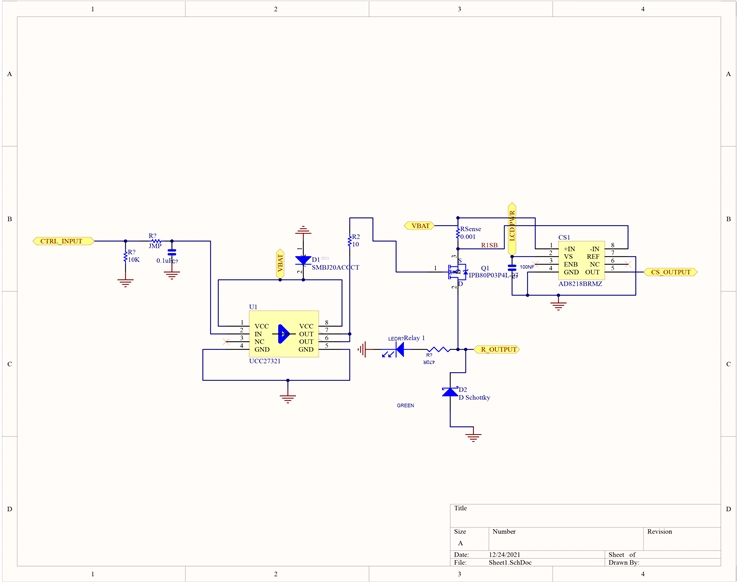
I am using a Ucc27321 gate drive to control IPB120P04P4L-03 mosfet @ 12volts driving resistive load. 

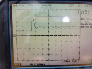
Issue is when testing device for short circuit control I get a large voltage spike across mosfet Source of about ~30 volts with about 30us duration.   The Source is tied to 12volt VCC that also powers UCC27321.  This causes UCC27311 to exceed Max voltage of 15V and therefore destroys UCC27321.

Short circuit test is conducted by tying Mosfet R Output to ground.  Processor turns Gate drive is turned on the senses current from AD8218 and turns gate back off within a 1ms.  Turn off causes pulse.

PCB is 4 layer with ground plane.

I have transient voltage suppressor SMBJ15A (15Volt) across VCC near UCC27321  , but it does nothing to keep spike below 15 volts.  

How can I protect UCC device?

t

  • Hi, FJ,

    Any stray inductance in your circuit builds up energy during the short circuit event, and when you interrupt the current flow, the stored energy is converted to the voltage spike you are seeing. Since your circuit seems to essentially be a DC switch circuit, there are some ways to help this issue.

    So, ways to overcome this:

    1. Reduce the stray inductance in your circuit

    2. Increase the local decoupling at the gate driver, and isolate it from your main 12V supply with 1-3 ohm resistance. A ferrite bead may also help isolate the spike from reaching our chip's power supply

    3. Increase the "stiffness" of your 12V rail to allow the energy to go back into the 12V supply without raising the voltage. You could do this by using a lower-output impedance power supply generating the 12V, and/or increasing the decoupling capacitors on your 12V supply

    4. Increase the gate resistor (shown as 10 ohms). This will slow down the switching speed, and may reduce the voltage spike at turn-off.

    You don't show any decoupling caps on your schematic, I assume you left them off for ease of viewing. Check out figure 30 for a recommended layout for the VDD cap to ground. Notice how nice and tight the loop is from VDD to Ground. Instead of tying the top via to your 12V supply, I would put another cap in parallel with C2 (1uF) and then tie that node to your 12V supply thru a resistor or ferrite bead.

    Let us know what you find.

    Best regards,

    Don

  • Thanks for the quit feedback.  Yes, this is just a piece of the entire circuit, there are more decoupling caps, but may not be enough.   

    Not sure where I am getting so much inductance on the output, or maybe you do not need that much inductance with a large current from short to cause that spike?

    I will try some of your suggestions.