This thread has been locked.

If you have a related question, please click the "Ask a related question" button in the top right corner. The newly created question will be automatically linked to this question.

UCC28730: Fault Issue. Overshoot and OVP?

Part Number: UCC28730
Other Parts Discussed in Thread: UCC24650

Hello

I tried looking around at some previous forum posts and SLUAAC5 "Flyback Aux Winding OVP and UVLO Fault Sensing Design and Troubleshooting Tips" (https://www.ti.com/lit/an/sluaac5/sluaac5.pdf) and can't seem to find my issue or the resolution.

I'm trying to implement the UCC28730 in a DC-DC converter with ultra-low standby. Targeting operation at 250VDC to 450VDC in and ~5.5V out (for LDO regulation to 5V then 3.3V and 1.2V for MCUs).
[See Spreadsheet]
The schematic for the circuit is above. The UCC24650 has been removed for testing.

RS1 (R2)  = 100k, RS2 (R7) = 30k, which should give me OVP threshold of ~7.1 OVP and Regulated Vout of ~ 6.2V according to SLUC579. Transformer datasheet here: au.mouser.com/.../760875112-1724366.pdf

Testing is mostly being done with 250VDC in. Some quick tests with 300VDC in didn't seem to have much of an effect. Startup voltage seems to be ~220VDC.

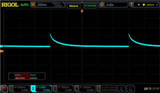
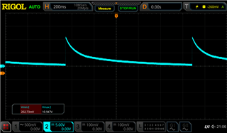
The device seems to be going into a fault state as evident by the VDD oscillating between the ~7V and ~21V UVLO on/off voltages and there is unacceptable output voltage regulation with overvoltage and excessive ripple. 

CH1 is VDD to HV-. CH2 is Vout (LV+ to LV-)

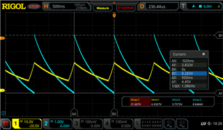
10k ohm output load. 


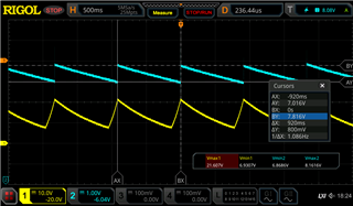
100k ohm output load


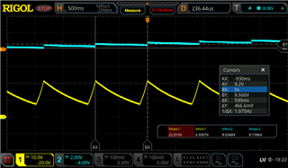
1 Meg ohm output load.

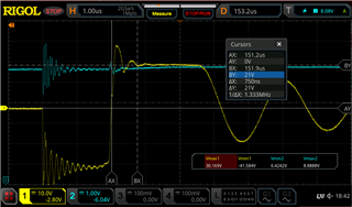
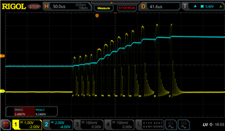
Zooming into the turn on transient, the VS seemed to be going over the 4.6V threshold for 3 consecutive cycles, causing OVP shutdown. Note there is some changing of the load values which affected the number of cycles but the waveform shapes and amplitude before shutdown where the same.

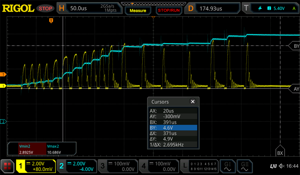
10k ohm load. CH1 is VS (probed with a x1 passive probe, 50pF +/-20pF) CH2 is Vout


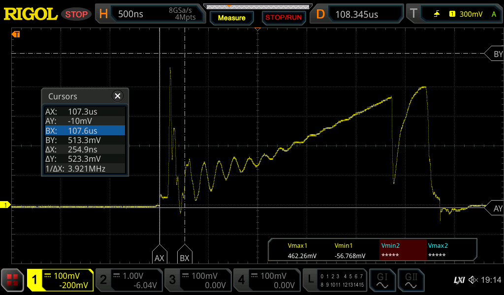
10k ohm load. CH1 is VS (probed with a x10 passive probe, 20pF +/-5pF) CH2 is Vout

I also checked for other potential fault conditions. As mentioned above, increasing the input voltage didn't seem to change anything.

Checked if the VDD cap is insufficient and dropping voltage triggering UVLO

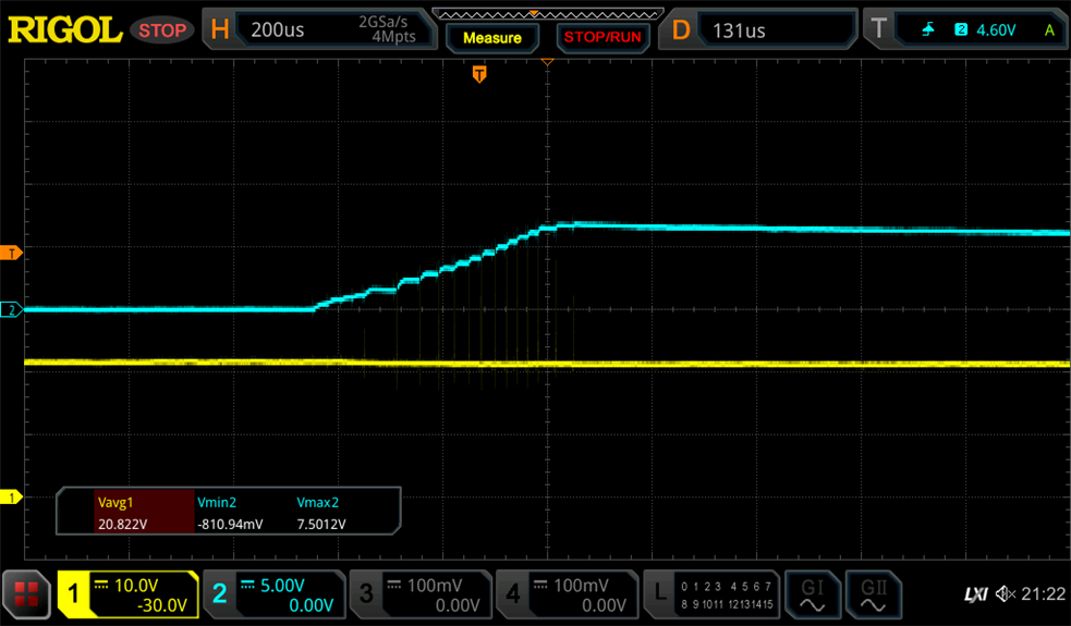
CH1 VDD, CH2 Vout. VDD does not appear to be getting exhausted and triggering a UVLO.

OCP also does not appear to be the issue.

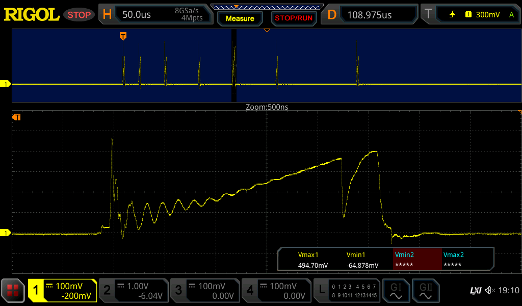
100k ohm load. CH1 is voltage across the current sense resistor (my R6= 1 ohm). The peak voltage observed is ~510mV ->510mA i.e. well below 1.5V OCP threshold.

The gate drive transient also appears to be well within the current sense leading edge blanking time (t_CSLEB=250nS). There also does not appear to be excessive or superfluous noise.

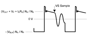
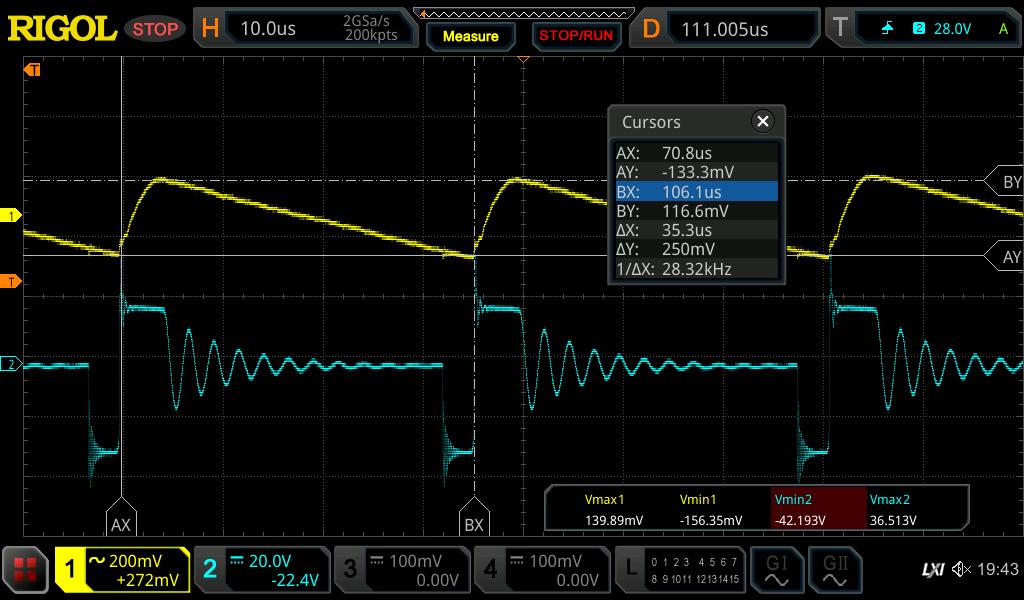
Taking a closer look at the Auxiliary winding waveform as recommended in documents now:

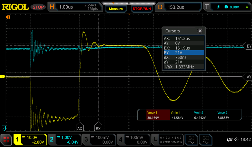
100k ohm load. CH1 is AUX (Aux diode D5 anode to HV-). CH2 is Vout.

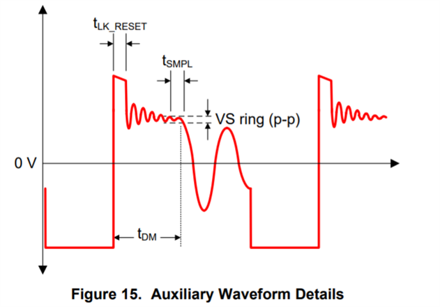
There does not appear to be excessive noise or ringing on the auxiliary waveform (apart from aux diode reverse bias ringing). The leakage inductance ripple/plateau appears to be sufficiently past the minimum. t_(LK_RESET)=750ns.


Taking a closer look at VS in the cycle before output voltage overshooting occurs:

CH1 VS, CH2 Vout. (x1 probing?)

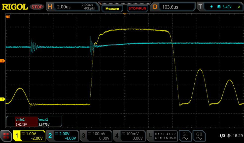
CH1 VS, CH2 Vout. (x10 probing)


The feedback signal looks quite "soft" with a very slow capacitive rise. This is likely due in part to probe loading but I wonder if this could be the issue, excess rise time on the VS pin causing issues in the output voltage measurement and overshooting into OVP. My only idea right now is to try adding capacitive bypassing to the VS voltage divider to try improve the VS frequency response but that could potentially cause more complications.

I am able to get it to run in light DCM without faults occurring (no VDD oscillation and good regulation) but this requires a relatively high load of 10 ohms (Vout ~6.6V, Iout 660mA) and this was fairly unstable with the switching period varying quite a bit and sometimes slipping back into the fault condition. Values from 10k ohm through 10 ohm (using a decade box) were also tested but it did not seem to operate without faults until ~10ohm load. 

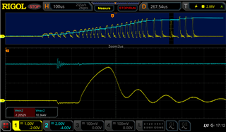
10 ohm load. CH1 Vout, CH2 Aux winding
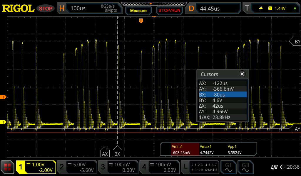
9 Ohm load. CH1 VS.

  • Hi, Ken:

    Thanks for reaching us. 

    It should be OVP. Based on your measurement, the Vaux,max is 21V which is higher than estimated. ( the coupling of transformer may be too good to make voltage is higher)

    So the Vs would be Vaux * R7/(R7+R2) = 21*30k/130k = 4.84V. It is over Vs,ovp, threshold, which is 4.52V~4.71V.

    Based on this, the Vs,ovp would be triggered. So you may calculate R7 based on the measurement results, 25kohm or lower to avoid the unexpected OVP. 

    Please modify it and see if it helps. 

    Would you please share me what system that UCC28730 used in? It is needed to use UCC24650 if the output loading is not stable. It would be a significant voltage drop once output load changes dramatically. 

    Regards, 

    Wesley

  • Thanks for the response Wesley

    I'm not sure lowering R7 (RS2) will help prevent the control loop overshooting. If my understanding of UCC28730 is correct, it will lower both the target regulation voltage and the OVP threshold. I previously had R7 replaced with a 20k potentiometer + 20k resistor soldered onto the board to try tuning the R7 value. Tuning the R7 value between 20k to 40k ohms didn't seem to change the issue apart from changing the number of cycles and the voltage level at which OVP was tripped. I note the setup with the pot+resistor soldered might have more parasitic inductance and capacitances than just a SMD resistor soldered in but the fault appears to be exactly the same.


    500 ohm load, pot at max (R7=~40k ohm). CH2 Vout.


    pot at min (R7=~20k ohm). CH2 = Vout

    (note UCC24650 was still installed during the above test runs)

    As for more notes on our application: the UCC28730 is being used as a DC-DC converter to supply a BMS and LCD screen inside a 250V to 450V battery system. We do intend to use the UCC24650 in the final implementation but have it removed currently to reduce the complexity whilst troubleshooting this OVP issue.

    Thanks and regards
    -Ken

  • Hi, Ken:

    I am not sure but it seems there is something wrong with your VS sensing. 

    As you mentioned, the output is 5.5V and R7 and R2 are designed according to this setting. 

    But the output is 6.6V when Rout is 10ohm, which is much higher than your setting, and the VCS signal is still not stable yet. 

    Please check your R1 setting and Vs trace first. You may increase R1 or adding a 100pF from CS to GND pin, and 10pF from Vs to GND to check if it helps. 

    Regards, 

    Wesley

  • Hello Wesley

    The design target was indeed Vout ~5.5V but the 6.6V measured under moderate load (4.3W) isn't too far off expectations given the RS1 and RS2 values used. The VCS signals provided also weren't for the 10ohm load condition. Regulation under moderate load conditions isn't my issue however.

    The issue is that under light load, the voltage overshoots heavily to >8.2V and causes a shutdown lasting ~1 sec during which the output is completely unpowered.

    Adding capacitance from VS to GND would likely worsen the overshooting issue by further attenuating the auxiliary winding feedback signal. This has also been partially tested when the VS to GND was probed with the oscilloscope passive probe (10pF to 50pF probe capacitance) and does not resolve the issue.

    Would you be able to refer this issue to a higher support tier?

    Regards
    -Ken

  • Attached is the SLUC579 "UCC28730 DESIGN CALCULATOR TOOL" spreadsheet with values used for the design.

    SLUC579_UCC28730 Design Calculator WE 760875112 - v0.1.xlsx

  • Hi, Ken:

    Thank you for providing the calculation file.  

    Since the response speed of PSR topology is slow, and output voltage raise very quickly in several pulse. UCC28730 may not response based on the output voltage in time to cause the overshoot and OVP. 

    May I know what kind of capacitors that you used as output?  It seems they are ceramic capacitors according to the schematic that you shared, and the output capacitance is lower than the calculation results, and DC bias may make Cout smaller if they are ceramic capacitors. 

    Would you please try to use E/C cap or other type to see if it helps? Or to increase the Cout to 2200uF which is the calculation results based on the calculation file. It may be a way to solve this.

    Please note an extra Rload might be still needed because of PSR operation. 

    Regards, 

    Wesley

  • Thanks for having a look Wesley.

    The output capacitors are indeed MLCC. Electrolytic capacitors aren't suitable due to application requirements: ultra-low leakage/standby current, vibration tolerance (Electrolytic cap weight), high reliability and size limitations. I can try adding in some more output capacitance with MLCCs to see if it helps stability. I note 150uF is the minimum required "with Wake-Up Monitor" per the calculation spreadsheet. My understanding was this requirement is more for limiting voltage drop due to load transients rather than control loop stability.

    Would it be acceptable to improve control loop response by adding a feed forward capacitor parallel to R2 (RS1) instead?

    I would hope significant max Rload (minimum load) is not a requirement for stability as the datasheet and device presentation (https://www.ti.com/lit/ml/slyp756/slyp756.pdf) advertise ultra-low (Pin <5mW) standby power and this was a major reason for us selecting the UCC28730.

    Regards
    Ken

  • Hi, Ken:

    Since the MLCC is sensitive to DC bias, the capacitance reduces a lot as DC bias increased. Thus, the effective capacitance would be less as it shows. For example, MLCC would decrease almost 80% of capacitance as 5VDC. The DC bias characteristic impacts MLCC a lot. If E/C cap is not allowed to use, maybe you can try other type capacitors which has less variation with DC bias. 

    For loop stability, the spreadsheet also suggests to have 1200uF to get 40' phase margin, and 2200uF is for voltage ripple spec. So I thought 1200uF is necessary if the voltage ripple is carelessness in this moment.

    And Rload is necessary since it is PSR technique. IC would generate a min pulse as fmin to sense output voltage through auxiliary winding because there is no voltage monitor circuit in 2nd side. If there is no Rload, the Vout would be charged by the sensing pulse. Normally it is needed a small loading current  (high Rload) to stabilize Vout. ( example: Rload is 100kohm of UCC28730EVM-552)

    Would it be acceptable to improve control loop response by adding a feed forward capacitor parallel to R2 (RS1) instead?

    It is not recommend.  Vs pin is using to sense the output voltage information from Vaux, and the sample point it the end of plateau of Vaux, and the response is controlled by internal units.. A feed forward capacitor may not help much but it would impact the shape of Vs. 

    Reduce Rs1 and Rs2 but keep the same ratio might be a safe way. It provides to higher current to ramp up Vs signal to IC but it impacts Vin(run) and line compensation. However, the key of response is still decided by internal control unit.  RS1 would not provide much improvement.  

    Regards, 

    Wesley

  • Thanks Wesley

    I'm aware of MLCC DC bias capacitance loss with non C0G dielectrics.

    I'll try with 1200uF capacitance and do some more tests to check the maximum Rload.

    Thanks for the note on the feed forward capacitor. Is there more information available on how the Aux voltage sampling works? I also note that RS1 is used for line voltage sampling and a feed forward capacitor could also affect the line voltage sensing function.

    Reducing RS1 and RS2 would not be acceptable due to the reduction in Vin(run) which is desired to prevent the power supply over discharging the battery.

    Regards
    -Ken

  • I performed some tests with increased output capacitance provided using low ESR electrolytic capacitors.

    Stability and proper operation (without overshoot and shut down) was achieved with a minimum of 220uF added capacitor and 15k ohm Rload.

    I'll be sure to use values well above this tested minimum in the final application. Currently considering 2x470uF and 10k ohm preload.

  • Hi, Ken:

    Is there more information available on how the Aux voltage sampling works?

    Did you mention when Vs sample the output voltage?

    The Vs pin would detect output voltage through Vaux after the blanking time. Vs pin keeps checking the voltage and use the last Vs voltage before the Vs drops significantly to be an input of control law. Since the Vs only keeps the voltage information before the slope changes. It is needed to keep the shape of Vs pin is as correct as possible.  

    Regards, 

    Wesley

  • Thanks for your feedback. I would like to close this thread since the issue solved. Thanks. 

  • Go ahead and close the topic. If I find any further issues I'll open a new topic but I think this problem has been solved. Thanks.