This thread has been locked.

If you have a related question, please click the "Ask a related question" button in the top right corner. The newly created question will be automatically linked to this question.

TPS2662: Power Rating for calculating Safety Factor for Intrinsic Safety

Part Number: TPS2662

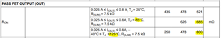
For my safety application I need to show that the part is being used at no more than 75% of rated power at the temperature it is used at.

The data sheet shows theta J parameters but does not say a max wattage nor does it say a temperature range that the theta J value runs between.
By setting max recommended operating condition of 125C, this would normally imply that power must be zero at 125C, but several lines of the data sheet show ratings for current at the full -40C to 125C range, so obviously this does not de-rate to zero power at 125C.

Please provide information that can help me calculate the "power derating line" from 0 power to full power.

Alternatively, if you say I can always go with max programmed current at 880mA (the current max) AT 125C then I could de-rate to 75% of 880mA and still run at 125C??

Thanks

Glen

  • Hi Glen,

    When carrying rated current of 800mA at 85C ambient, the temperature rise in the device is I^2*Rds_max*RθJA = (0.8*0.8*685mOhm*44.8C/W)= 19.64 C. The effective junction temperature is at 85+19.64 = 104.64 C

    Similarly, we can back calculate how much we need to de-rate the current while operating at 125C with temperature rise of 20C

    20C = (k*I)^2*Rds_max*RθJA

    where k*I is the derated current

    20C = (k*I)^2*Rds_max*RθJA = (k*I)^2*800mOhm*44.8C/W)  solving give k*I as  747mA

    Derating factor =(1-747/880)*100=> de-rate by 15%

    Best Regards, Rakesh

  • Hello Rakesh

    Thank you for your response.  However, I think there is more.

    1) Where does the 85C come from?  At the top of section 7.5, the various currents are shown for 125C conditions.

    2) You are calculating power with max RDSon, but I can tell the part throttles current over a certain range before starting to cycle.
    I have observed this on the bench when I load the part.  There is always a transition period where the transistor starts to shut off, the output voltage drops a bit and then finally with a bit more load it starts cycling.

    From the data sheet, I can see this is either 1V or 2.6V drop..
    The top of page 7 of the data sheet shows max currents with a 1V drop.  (and at 125C)
    But...7.6 under "CURRENT LIMIT" shows tripping at <2.6V which would maybe imply the part will throttle current somewhere in the 1-2.6V range before starting to cycle.  And that would then be 800mA x1V = 0.8W min or 2.6 x 0.8A = 2.08W which is quite a range.
    And again, the data sheet has all this in the 125C max section.  No mention of 85C.
    Yes, there is a FET resistance at 85C but also one at 125 and 0.8A.

    So I need some more clarity.

    Either it is rated at 800mA at 125C and I de-rate current
    OR
    The package has a wattage rating and there is a max voltage drop used to calculate the wattage.

    Thanks

    Glen

  • Hi Glen,

    I gave calculation examples at various operating conditions in steady state condition. The voltage drop you are referring happens only when the device starts current limiting.

    If you are looking for the amount of power dissipation the device can handle during current limit before going into thermal shutdown. Please refer figure 7-23 in the datasheet. The time to shut down depends on the operating temperature, power dissipation and board thermal parameters.

    Please go through https://e2e.ti.com/support/power-management-group/power-management/f/power-management-forum/1053287/faq-tps2660-how-much-time-does-the-efuse-takes-to-thermal-shutdown-during-overcurrent-fault 

    Best Regards,

    Rakesh