A related question is a question created from another question. When the related question is created, it will be automatically linked to the original question.
If you have a related question, please click the "Ask a related question" button in the top right corner. The newly created question will be automatically linked to this question.
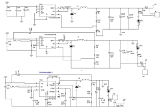
TPS5450: inverted and non inventer supply using TPS5450
Have you also tried looking at the alternative LM61460 device? The TPS5450 is a relatively older device and it is recommended to move to newer devices if supply is available.
For the IBB designs U104 and U106, how much load current is expected from the application? Also can you fill out what the inductor values are? It is not detailed in the schematic.
Following Section 4.1 of the app note, the voltage stress the TPS5450 can experience should be limited to the maximum input voltage range. This means that for a -15V output rail, the maximum input voltage should be no more than 20V.
Also can you fill out what the inductor values are? It is not detailed in the schematic.
>>>>L7/L8/L9 = 10uH,5A,21mohms
Following Section 4.1 of the app note, the voltage stress the TPS5450 can experience should be limited to the maximum input voltage range. This means that for a -15V output rail, the maximum input voltage should be no more than 20V.
>>>>Input supply is nominal=20v, while output is fixed =-15v. so is this okey with TPS54060 ?
>>>> for whole design, the common ground is used...is that okey? can you share the layout guide also...